Application of Ground-Penetrating Radar to Mapping Archaeological Features at the Gould Site, Port au Choix
Trevor BellMemorial University
Julian Daly
University of Maine at Farmington
Alice Kelley
Department of Earth Sciences at the University of Maine in Orono
M. A.P. Renouf
Archaeology Unit of Memorial University
INTRODUCTION
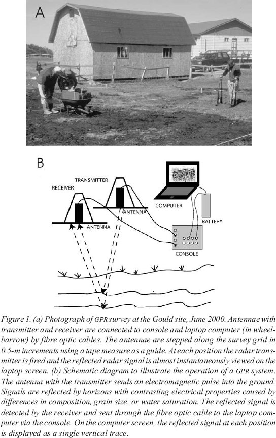
1 GROUND-PENETRATING RADAR (GPR) is a geophysical technique used to help identify and characterize archaeological sites prior to excavation. GPR is particularly well suited to archaeological surveys because it provides a nondestructive, rapid way to provide continuous high-resolution profiles across a site. Because all information is acquired at the ground surface, there is no disturbance of buried cultural material. Data are collected at a walking pace, permitting a large area to be surveyed relatively quickly, particularly when compared to the amount of time required for hand excavation (Figure 1a). Although post-collection processing of the data is possible, and in most cases is desirable, many systems provide the almost immediate creation of a paper or electronic version of the survey record, allowing the investigator to review data in the field. This feature allows the survey pattern to be altered or refined immediately to allow closer investigation of anomalous areas. Application of standard values for electromagnetic wave propagation rates calculated for a variety of materials permits two-way travel times to be converted to depth rapidly, and aids in archaeological assessment of a site while in the field.
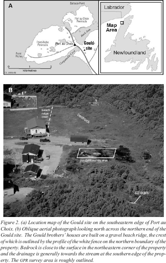
2 In this paper we explore the application of GPR to the pre-excavation analysis on an area of the Gould Site (EeBi-42), Port au Choix (Figure 2a). Earlier excavations at the site provided “ground truth” for on-site survey decisions. Excavations after the GPR survey allowed testing of data interpretation.
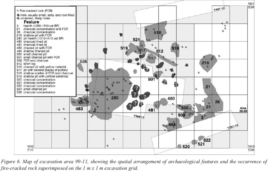
Figure 1. (a) Photograph of GPR survey at the Gould site, June 2000. Antennae with transmitter and receiver are connected to console and laptop computer (in wheelbarrow) by fibre optic cables. The antennae are stepped along the survey grid in 0.5-m increments using a tape measure as a guide. At each position the radar transmitter is fired and the reflected radar signal is almost instantaneously viewed on the laptop screen. (b) Schematic diagram to illustrate the operation of a GPR system. The antenna with the transmitter sends an electromagnetic pulse into the ground. Signals are reflected by horizons with contrasting electrical properties caused by differences in composition, grain size, or water saturation. The reflected signal is detected by the receiver and sent through the fibre optic cable to the laptop computer via the console. On the computer screen, the reflected signal at each positionis displayed as a single vertical trace.Figure 2. (a) Location map of the Gould site on the southeastern edge of Port au Choix. (b) Oblique aerial photograph looking north across the northern end of the Gould site. The Gould brothers’ houses are built on a gravel beach ridge, the crest of which is outlined by the profile of the white fence on the northern boundary of the property. Bedrock is close to the surface in the northeastern corner of the property and the drainage is generally towards the stream at the southern edge of the property. The GPR survey area is roughly outlined..GROUND-PENETRATING RADAR AND ARCHAEOLOGY
3 GPR was developed in the 1960s as part of the United States lunar exploration programme and has been used in a variety of engineering and geological applications (see Conyers and Goodman 1997 for an overview). A high-frequency electromagnetic signal is sent through the subsurface. If that signal encounters a change in the electromagnetic properties of the subsurface material, some of the signal energy is reflected back to the surface where it is detected by a receiver (Figure 1b). Reflections are the result of changes in lithology, water saturation, density, grain size, or porosity (Conyers and Goodman 1997).
4 GPR is a useful tool for the initial characterization of an archaeological site. It allows a rapid investigation of the site stratigraphy and the depth to bedrock, and may suggest the location of buried cultural resources such as gravesites, walls, or other areas of buried ground disturbance or cultural features. GPR can be used in site delineation, and is an efficient means to investigate the correlation between historical accounts and cultural remains. For example, Vaughan (1986) used GPR to locate graves at a sixteenth-century Basque whaling station in Labrador. Earlier excavations had located some interments, and GPR was used to survey an adjacent area prior to excavation. The graves were dug in beach gravels and covered with peat. Although the grave fill materials did not differ greatly from the surrounding strata, the ground disturbance created by burial activities had different electromagnetic properties, and appeared as interrupted strata on the GPR record. Subsequent excavation showed good correlation between recognized anomalies and burial sites. The peat-covered remains of cobble walls from Basque structures were also recognizable on the GPR records. Large whale vertebrae also created anomalous returns.
5 Peatland studies have used GPR to locate the base and thickness of peat deposits (Lowe 1985; Warner et al. 1990; Pelletier et al. 1991; Jol and Smith 1995). GPR has also been used to identify ash and wood layers in peat (Theimer et al. 1994). Peat stratigraphy can be differentiated by GPR on the basis of the degree of humification (decomposition; Lowe 1985; Warner et al. 1990) and on peat composition (Hanninen 1992).
THE GOULD SITE
6 The Gould site covers an area of about 1.5 hectares at the southern margin of the town of Port au Choix (Figure 2a), and is named for the property owners. The northern part of the site is situated on a broad, level terrace 6-10 metres above sea level. Limestone is exposed at the back of the terrace in the northeast corner of the site, and dips abruptly seaward to the west and more gently to the south and southwest. The Gould brothers’ houses are located on a gravel beach ridge on the outer edge of the terrace (Figure 2b). The central part of the site occupies a broad depression between the bedrock slope and the gravel beach and is currently drained by a stream to the south.
7 The site comprises two cultural and three temporal components. The earlier component is Maritime Archaic Indian (MAI), which consists of two separate occupations, the earlier dating to 6290-6210 cal BP1 and the later dating from 4800 to 3340 cal BP. A third component, Recent Indian, dates from 2110 to 1330 cal BP. The stream divides the Gould site into southern and northern parts. These areas are culturally separate: the older MAI component is located in the southern area, and the younger MAI and the Recent Indian components are found in the northern area. The
8 GPR survey was conducted in June 2000 in a 325-square-metre area behind John Gould’s house in the northern area (Figure 2b).
SITE STRATIGRAPHY
9 Limestone of the Middle Ordovician Table Point Formation comprises the base of the geologic section at the Gould Site. It consists of well-bedded, dark grey, fossiliferous limestone with dolomitic and argillaceous seams (Figure 3a; Knight 1991). The bedrock is overlain by stratified pebble gravel (Figure 3b), interbedded with coarse sand and marine shells, and by stony mud containing weathered limestone clasts and marine shells (unit 5; Figure 3). The stony mud is interpreted as a near-shore, possibly back-barrier, lagoonal deposit, whereas the dipping gravel and sand composes the main beach ridge facies (Renouf and Bell 2000). Radiocarbon dates on shells from the gravel at 9 and 5.6 metres above sea level provided ages of 8430 and 4240 cal BP, respectively, indicating that the site slowly emerged from the sea over this time (Bell et al. this volume). A greyish white fine sand layer, millimetres to centimetres thick, drapes the underlying mud/gravel. This unit is, in turn, overlain by grey-black silty clay containing extremely fine disseminated organic material and some macrofossils (unit 4; Figure 3c). This unit is rarely more than 10-15 centimetres thick, and is dated 4260-5590 cal BP. This layer is interpreted to be the earliest soil horizon at the site.
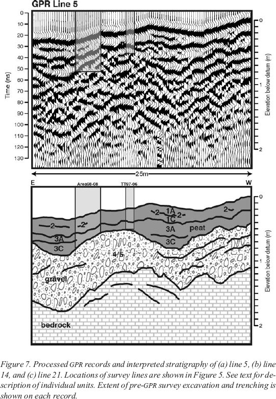
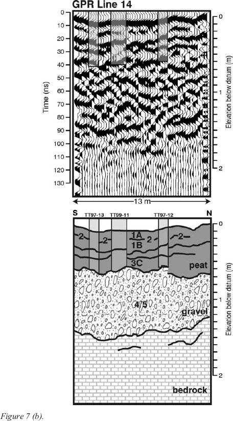
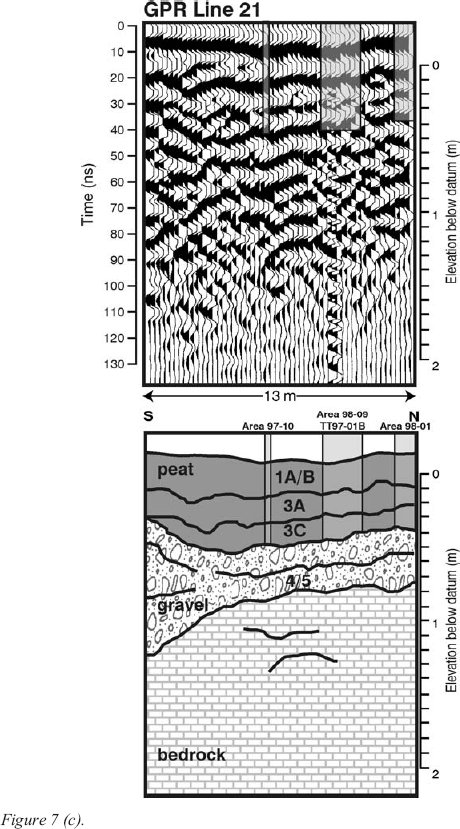
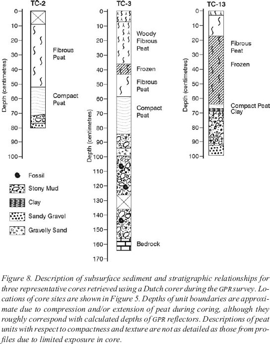
10 A two-unit sequence of peat dominates the upper stratigraphy of the Gould site north (units 1 and 3); each unit is further divided into two subunits (units 1A, 1C, 3A, 3C; Figure 3). The total peat cover varies in thickness from 60 to 130 centimetres across the site, but an unknown thickness has been removed from the surface due to forest clearance and site development. The lowermost peat (unit 3C; Figure 3c) has a high organic content (85-95%), and is highly humified, resulting in poor preservation of macro-remains, although wood fragments, bark and woody roots are present in the upper portion of the unit (Vardy 2000). Unit 3A is a reddish-brown peat, which has a gradational to distinct contact with the underlying unit (Figure 3c). Individual fossils are clearly distinguishable, with macrofossils becoming larger and peat becoming less compact at higher stratigraphic levels. In some places, this unit parts easily into layers. The overlying peat (unit 1; Figure 3c) is coarse and fibrous, with large organic pieces such as twigs and branches clearly visible. This layer contains a cultural horizon dated at 1300 cal BP, which divides it into two subunits (A and B; Figure 3). A 5-centimetre-thick layer of disturbed peat tops the sequence.
Figure 3. Stratigraphic profiles mapped along the walls of selected test trenches in the study area. Profile locations are identified in Figure 5. In some cases the surface represents an excavated level, not the original ground surface. The points of intersection of GPR survey lines and the profile wall are indicated. Nearby coring locations are also shown, but note that they rarely coincide with the walls of test trenches. Core locations are shown on Figure 5, whereas core stratigraphy is presented in Figure 8. Photographs A to C highlight the peat stratigraphy of the Gould site (from Area 98-2), the beach gravel underlying the peat (shovel is 110 cm high), and the weathered limestone surface, respectively. See text for description of individual units.CULTURAL STRATIGRAPHY
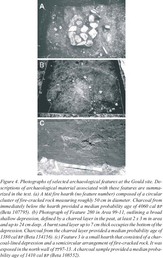
11 The cultural stratigraphy of the Gould site is straightforward. The older MAI material lies on or just above the beach sediments in a clayey matrix (unit 4; Figure 3). Archaeological features such as hearths are built into the surface of the beach sediment (Figure 4a) and materials associated with them have been dated between 4420 and 1400 cal BP (Renouf and Bell 2000). Evidence of Recent Indian occupations is found within the upper peat layer, and consists of dark grey-black charcoal fragments associated with chert flakes and tools (unit 2; Figures 3, 4b and 4c). The cultural layer is of variable thickness, from 1 millimetre to greater than 10 centimetres, reaching its maximum where large fire-cracked boulders are present. A sample of charcoal from a nearby fire hearth in this layer provided a date of 1520-1350 cal BP (Renouf and Bell 1999). Careful tracing of the roots and trunks of small trees in this layer indicates that the area was forested at the time of Recent Indian occupation, and that some of the trees were cut and the stumps not removed. Excavations in Area 99-11 identified several hearths, potential post-holes marking the site of a small dwelling, and numerous artifacts (Figures 5 and 6). These findings are described in more detail below.
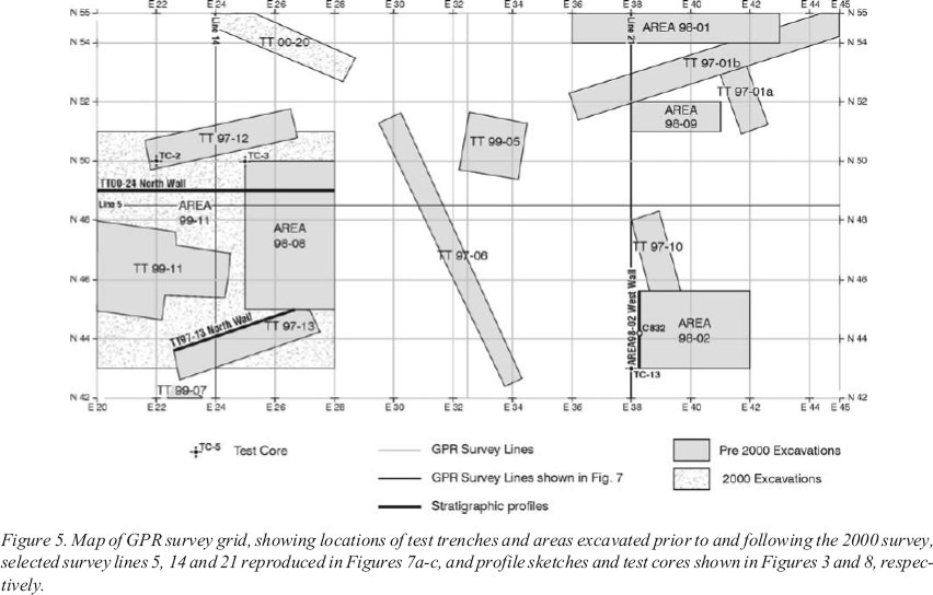
12 In 1997, several 1-metre by 5-metre test trenches were excavated in and around the Gould site as part of an initial archaeological site survey. A small well-defined hearth (Feature 3; Figure 4c), approximately 1 metre in diameter and 20 centimetres deep, was found in the peat in Test Trench 97-13 in John Gould’s backyard, and a ground slate whetstone was found in nearby Test Trench 97-12 (Figure 5). On the basis of these discoveries, a 3-metre by 2-metre area was excavated between the two test trenches in 1998 (Area 98-08; Figure 5). An 8-metre by 12-metre area was opened in the same area in 1999 and 2000 (Area 99-11; Figure 5).
13 A large shallow burned pit (Feature 280; Figure 4b), measuring at least 2 metres by 3 metres and 24 centimetres deep was found in the centre of this area (Figures 5 and 6). The bottom of the pit was lined with a 7-centimetre-thick layer of burned sand. Many large, fire-cracked rocks, dozens of ceramic sherds, many Recent Indian stone tools, and thousands of small retouch flakes from tool sharpening were found in and stratigraphically above the sand layer. Several small holes, potentially post-holes, may mark the boundary of a dwelling structure associated with the pit. Teal (2001) interprets the pit, and surrounding pattern of flakes, fire-cracked rocks, and small post-holes and holes as the remains of a small dwelling, probably a tent.
Figure 4. Photographs of selected archaeological features at the Gould site. Descriptions of archaeological material associated with these features are summarized in the text. (a) A MAI fire hearth (no feature number) composed of a circular cluster of fire-cracked rock measuring roughly 50 cm in diameter. Charcoal from immediately below the hearth provided a median probability age of 4060 cal BP (Beta 107795). (b) Photograph of Feature 280 in Area 99-11, outlining a broad shallow depression, defined by a charred layer in the peat, at least 2 x 3 m in area and up to 24 cm deep. A burnt sand layer up to 7 cmthick occupies the bottom of the depression. Charcoal from the charred layer provided a median probability age of 1380 cal BP (Beta 134156). (c) Feature 3 is a small hearth that consisted of a charcoal-lined depression and a semicircular arrangement of fire-cracked rock. It was exposed in the north wall of TT97-13. A charcoal sample provided a median probability age of 1410 cal BP (Beta 108552).
Display large image of Figure 4
Display large image of Figure 5
Display large image of Figure 6
14 Feature 484 is located near the southern edge of Area 99-11 and is adjacent to Feature 3 (Figure 6). Feature 484 is a shallow charred pit or depression containing several pieces of fire-cracked rock, some flakes and a few Recent Indian artifacts. It measures at least 88 by 97 centimetres, and was possibly truncated by Test Trench13. Features 3 and 484 do not appear to be the same feature, but both were likely associated with the same suite of activities that took place outside the dwelling.
GROUND-PENETRATING RADAR SURVEY DESIGN
15 Data were collected using Sensors & Software pulseEKKO IV equipment. The 200-megahertz antennae were spaced 0.5 metres apart, and shots were taken every0.25 metres along a survey grid (Figures 1a and 5). The returned data from each shot (the traces) were stacked 64 times to amplify potentially small but important signals from cultural artifacts. Survey lines were designed to overlap with the previously established archaeological grid (Figure 5). Each line was surveyed to determine subtle changes in topography that might affect the shape of reflections.
POST-COLLECTION PROCESSING
16 The data were ground-truthed using several methods. A common-midpoint profile (CMP) collected on site was used to determine the velocity of the upper layers of peat. CMPs also indicate whether a reflector is “real” or caused by interference with the signal. Real reflections have a characteristic hyperbolic shape, and the arrival time of the reflection at a certain distance is used to determine the velocity of the subsurface material. In addition, data were collected along a transect crossing a bedrock outcrop, so that the reflection from the bedrock surface could be traced directly in the subsurface. Several auger cores were collected, and the lithologic divisions correspond well with reflections in the radar records.
17 The data were processed to amplify reflections and minimize noise. A filter was applied to each trace to smooth it slightly and each trace was averaged with an adjacent trace. A “dewow” correction was also applied to each line to minimize ringing in the signal that was probably related to the high electromagnetic contrast between the bedrock and overlying materials. This processing effectively amplifies signal and removes high-frequency noise. Changes in the topography of the surface are taken into account by applying a topographic correction using levelled data along each transect.
18 Shallow subsurface bedrock (<2 m depth) limited the depth of signal penetration. Although there were deeper signals recorded in several records, cores collected along transects and the CMP indicate that these were not real events. The average velocity of the subsurface material is estimated from the CMP survey to be0.035 metres/second, comparable to published values for saturated peat (Jol and Smith 1995). The depth axis on the GPR plots was calculated using this velocity. It is important to note that this velocity is an average value for the unconsolidated material from the surface to the top of the bedrock, and does not take into account velocity differences between subsurface layers that may result from lithologic contrasts or degree of water saturation.
19 One of the objectives of this study was to test the ability of GPR to detect items of archeological interest (fire-cracked rocks, thin anthropogenic layers). The resolution of subsurface features is a function of the radar frequency and the depth to the buried object, so individual objects or layers may be too thin to be resolved. At depth, each radar pulse images an elliptical area. The dimensions of this ellipse depend on the frequency of the antennae and the depth below the surface (near the surface, the ellipse is smaller) (Widess 1973). Rocks (if large enough) and other individual items surrounded by peat produce hyperbolic reflection patterns (Daniels 1989). The limit of detection is a function of antenna frequency and electromagnetic contrast between items of interest and surrounding material. For 200-megahertz antennae, the minimum detectable thickness of a layer (or an object) is 0.12 metres; layers thinner than this (or objects smaller than this) are not likely to be detected by the system (Annan and Cosway 1992).
GROUND-PENETRATING RADAR STRATIGRAPHY
20 GPR investigation revealed several consistent reflectors and units across the study site. The major reflectors are interpreted to be the upper surface of the bedrock, the contact between beach sediments and overlying peat, and several internal reflectors within the peat. The beach and peat materials have characteristic reflection patterns, and can be defined as stratigraphic units in the context of the GPR data (Huggenberger 1993)
21 On each of the GPR records the lowest (basal) continuous reflector appears strong and irregular, dipping from west to east across the site, and reaching a maximum depth below the ground surface of 2 metres (Figure 7). This reflector is interpreted to be the bedrock surface because of its similarity to the known radar reflectance characteristics of the local bedrock. Core TC-3 provides support for the interpretation of this reflector as the bedrock surface (Figures 5 and 8). Few coherent reflectors are apparent below the bedrock reflector, although there appear to be many small hyperbolic reflectors associated with its surface. These hyperbolae result from the interaction of the radar with the irregular surface of the limestone, which tends to weather with typical karst dissolution features (Figure 3).
Figure 7. Processed GPR records and interpreted stratigraphy of (a) line 5, (b) line 14, and (c) line 21. Locations of survey lines are shown in Figure 5. See text for description of individual units. Extent of pre-GPR survey excavation and trenching is shown on each record.
Display large image of Figure 7
Display large image of Figure 7(b)
Display large image of Figure 7(c)
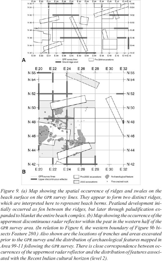
22 The strong basal reflector is overlain by a unit of variable thickness, which is characterized by short, discontinuous, moderate to strong chaotic reflectors. These reflectors are associated with the beach sand, gravel, and stony mud described in core (Figures 5 and 8) and examined in local exposures (Figure 3). Discontinuous dipping reflectors within this unit are interpreted as representing bedding within the gravel (Figure 7a, b and c). This unit is bounded above by a strong, continuous reflector that displays a hummocky profile on some GPR lines. Spatial mapping of these hummocks across the site reveals a consistent pattern of ridge and swale, oriented roughly northwest-southeast (Figure 9a). These are interpreted as beach berms with a relief of 40-50 centimetres developed on the sandy gravel surface. They are roughly parallel to the main beach ridge on which the Gould brothers’ houses are built (Figure 2a), although they are of much smaller magnitude. The reflector is therefore interpreted to be the contact between the beach sediment and overlying peat, and is defined as the basal peat reflector.
23 The basal peat reflector likely represents marked changes in material texture which is transitional from compact peat at the top of this unit (unit 3C) through relatively thin clay and sand layers (unit 4), representing the MAI cultural horizon on a buried soil, to the underlying beach sediments below (unit 5). The boundary between the peat and soil may represent the strongest difference in electromagnetic properties, and therefore the strongest radar reflectance. This is attributed to the abrupt textural change and low porosity, impermeable nature of the clay surface on which the MAI cultural level is located. Compaction due to trampling during occupation may also contribute to the dense nature of this horizon. Fire-cracked rock observed resting within and along the contact between units 3 and 4 in excavations (Figure 3) were not detected on the GPR profiles, probably because of their size relative to the detection limit of the radar system (<12 cm diameter).
24 A mixture of continuous to discontinuous strong reflectors characterizes the internal structure of the peat. The lowermost reflector is only recorded between beach berms and appears to pinch out against them (Figure 7a and c). The middle reflector is the strongest and most continuous one in the peat, and clearly blankets the underlying beach topography. The uppermost reflector in the peat is discontinuous and less pronounced than the other two and roughly parallels the ground surface.
25 Exposed walls of archaeological test trenches and excavations, along with test cores taken from the surface, provide profiles through the peat stratigraphy that allow correlation with the radar reflection profiles (Figures 3 and 8). The lowermost reflector appears to correspond with the contact between peat subunits 3A and 3C (Figure 3; Area 98-2 West profile) and is likely caused by a change in peat compaction and texture. Unit 3A is interpreted to be a fen peat that accumulated in depressions between beach ridges, whereas unit 3C is a woody peat that blankets the entire beach ridge complex (Vardy 2000).
Figure 8. Description of subsurface sediment and stratigraphic relationships for three representative cores retrieved using a Dutch corer during the GPR survey. Locations of core sites are shown in Figure 5. Depths of unit boundaries are approximate due to compression and/or extension of peat during coring, although they roughly correspond with calculated depths of GPR reflectors. Descriptions of peat units with respect to compactness and texture are not as detailed as those from profiles due to limited exposure in core.
Display large image of Figure 8
26 The transition from peat units 3 to 1 also reflects a change in the compactness of the peat, which is readily identified in the field (e.g., Figure 3, Area 98-02 West Wall; Figure 7c). Although in places disrupted by previous excavations and test trenching, this contact appears continuous on the GPR record, perhaps due to local water retention along the top of the compact peat, giving it the appearance of an intact unit.
Figure 9. (a) Map showing the spatial occurrence of ridges and swales on the beach surface on the GPR survey lines. They appear to form two distinct ridges, which are interpreted here to represent beach berms. Peatland development initially occurred as fen between the ridges, but later through paludification expanded to blanket the entire beach complex. (b) Map showing the occurrence of the uppermost discontinuous radar reflector within the peat in the western half of the GPR survey area. (In relation to Figure 6, the western boundary of Figure 9b bisects Feature 280.) Also shown are the locations of trenches and areas excavated prior to the GPR survey and the distribution of archaeological features mapped in Area 99-11 following the GPR survey. There is close correspondence between occurrences of the uppermost radar reflector and the distribution of features associated with the Recent Indian cultural horizon (level 2).
Display large image of Figure 9
27 Pollen data suggest that although wooded peatland persisted through the record of peat unit 1, there were extended periods of dry conditions, as indicated by increased heath (cf. Ericaceae) and shrub pollen and decreased fern pollen (Vardy 2000). Whether or not the upper horizons noted on the GPR profiles also correspond to this change in peat composition is not known; however, these periodic dry conditions would permit habitation of the peatland during these intervals.
28 The most archaeologically significant of the internal reflectors in the peat is the discontinuous, less pronounced reflector at 10 to 20 centimetres depth that roughly parallels the ground surface. Breaks in the reflector typically correlate with previously excavated areas or test trenches, which interrupted the original stratigraphy (Figure 7b). This reflector is interpreted to represent the Recent Indian cultural horizon. Close correspondence of this reflector with the mapped cultural level (L2) in test trenches (TT97-13, TT00-24; Figures 3, 5 and 9b) confirms our interpretation. Although this horizon in the peat is relatively thin, it represents a trampled, compact surface with abrupt increases in mineral sediment and charcoal, fire-cracked rock (although not individually imaged due to resolution), artifacts (e.g., pottery sherds, flakes) and animal hide (Teal 2001), which together presents a moderately reflective surface for GPR. It is believed that the change in peat electromagnetic properties resulting in a strong GPR reflector is largely the result of human activity in this location. The spatial occurrence of this reflector is mapped on Figure 9b. It indicates where excavations in 2000 should have encountered the Recent Indian cultural horizon and other areas that may conceal this horizon but remain unexcavated. The features and fire-cracked rock mapped in Area 99-11 (Figure 6) show a close correspondence with the reflector occurrence on the GPR grid, which gives us a certain degree of confidence that the presence/absence of the Recent Indian cultural horizon can be predicted from the GPR survey.
CONCLUSIONS
29 This study illustrates the application of GPR to the analysis of archaeological sites. Due to the rapid and non-destructive manner of data collection, GPR is a useful subsurface mapping tool for initial evaluation and correlation of site stratigraphy. The highlights of the GPR survey at the Gould site may be summarized as follows.
30 Identification and mapping of major stratigraphic units including bedrock, beach sediment, and peat: radar reflection patterns within these units are directly linked to mode of deposition.
31 Mapping of beach surface topography: Maritime Archaic Indians occupied partially vegetated beach ridges prior to peat accumulation on the site. GPR profiles provide information on ridge occurrence, orientation, and relief, which may have partly dictated the spatial pattern of cultural activities on the site. For example, ridge crests would have better drainage and therefore would be more suitable for dwellings.
32 Detecting fire-cracked rock: Although there is an abundance of fire-cracked rock on the site (both MAI and Recent Indian components), individual rocks cannot be identified using the 200- megahertz frequency GPR antennae. Higher frequency antennae may be more successful in this regard, but it is possible that the strong radar reflection from the peat-gravel contact may obscure individual archaeological targets resting on the beach surface.
33 It is not surprising that radar reflectors within the peat record variations in texture, compactness, and geoelectrical properties (e.g., Theimer et al. 1994). Of greater archaeological significance, however, is the identification of a Recent Indian cultural level within the peat. Although relatively thin (<24 cm thick), the combination of introduced mineral sediment (sand and fire-cracked rock), fire charcoal and charred peat, and trampling and compaction of the peat surface at this level likely results in a strong and mappable radar reflection. A map displaying the distribution of this discontinuous reflector appears to closely correspond with the distribution of features and artifacts associated with the Recent Indian cultural level exposed through later excavation. Because the only distinction between this “cultural” reflector and other “geological” reflectors in the peat is its spatial discontinuity, GPR cannot effectively be used to prospect for cultural horizons within peat; however, it may be extremely useful in mapping the distribution and stratigraphical context of a known cultural horizon in peat.
Acknowledgements
Multi-year funding has been provided by the Natural Sciences and Engineering Research Council of Canada, the Social Sciences and Humanities Research Council of Canada, Parks Canada, and Memorial University of Newfoundland. We would like to thank Shane Greene for field assistance. Diagrams were drafted by David Mercer and Charles Conway, Memorial University of Newfoundland Cartography Laboratory. Comments by two reviewers are gratefully acknowledged.References
Annan, A.P. and S.W. Cosway (1992), “Ground-penetrating radar survey design.” Proceedings of the Symposium on the Application of Geophysics to Engineering and Environmental Problems (SAGEEP), pp. 329-352. Environmental and Engineering Geophysical Society, Denver, CO.
Bell, T., I.R. Smith, and M.A.P. Renouf (this volume), “Postglacial Sea-Level History and Coastline Change at Port au Choix, Great Northern Peninsula, Newfoundland.”
Conyers, L.B. and D. Goodman (1997), Ground-Penetrating Radar: An Introduction for Archaeologists. AltaMira Press.
Daniels, J.R. (1989), “Fundamentals of ground-penetrating radar.” Proceedings of the Symposium on the Application of Geophysics to Engineering and Environmental Problems (SAGEEP), pp. 62-142. Environmental and Engineering Geophysical Society, Denver, CO.
Hanninen, P. (1992), “Application of Ground-penetrating radar techniques to peatland investigations .”In Geological Survey of Finland Special Paper 12, pp. 159-162.
Huggenberger, P. (1993), “Radar facies: recognition of facies patterns and heterogeneities within Pleistocene Rhine gravels, NE Switzerland.” In Braided Rivers, edited by J.L. Best and C.S. Bristow, pp. 163-176. Geological Society Special Publication No. 75.
Jol, H.M. and D.G. Smith (1995), “Ground-penetrating radar surveys of peatlands for oil-field pipelines in Canada.” Journal of Applied Geophysics 34: 109-123.
Knight, I. (1991), Geology of Cambro-Ordivician Rocks in the Port Saunders (NTS 12I/11), Castors River (NTS 12I/15), St. John Island (NTS 12I/14) and Torrent River (NTS 12 I/10) Map Areas. Report 91-4, Geological Survey Bramch, Department of Mines and Energy, Government of Newfoundland and Labrador.
Lowe, D.J. (1985), “Application of impulse radar to continuous profiling of tephra bearing lake sediments and peats: An initial evaluation.” New Zealand Journal of Geology and Geophysics 28: 667-674.
Pelletier, R.E., J.L. Davis, and J.R. Roissiter (1991), “Peat analysis in the Hudson Bay Lowlands using found penetrating radar. ”In GARSS ’91: Remote sensing; global monitoring for earth management, pp. 2141-2144. Institute for Electrical and Electronic Engineering.
Renouf, M.A.P. and T. Bell (1999), Report of the Port au Choix Archaeology and Sea Level History Project Preliminary Report of the 1998 Field Season. Ms. on file, Provincial Archaeology Office, Government of Newfoundland and Labrador, St. John’s.
Renouf, M.A.P. and T. Bell (2000), Gould Site, Port au Choix, 1999 Report of Field Activities. Ms. on file, Provincial Archaeology Office, Government of Newfoundland and Labrador, St. John’s.
Teal, M.A. (2001), “An Archaeological Investigation of the Gould Site (EeBi-42) in Port au Choix, Northwestern Newfoundland: New Insight into the Recent Indian Cow Head Complex.” MA thesis, Archaeology Unit, Memorial University of Newfoundland.
Theimer, B.D., D.C. Nobes, and B.G. Warner (1994), “A study of the geo-electrical properties of peatlands and their influence on ground-penetrating radar surveying.” Geophysical Prospecting 42: 179-209.
Vardy, S.R. (2000), Palaeobotanical analysis of peat and lake sediments, Port au Choix Archaeology and Sea Level Project. Unpublished report, Memorial University of Newfoundland.
Vaughan, C.J. (1986), “Ground-penetrating radar surveys used in archaeological investigations.” Geophysics 51 (3): 595-604.
Warner B.G., D.C. Nobes, and B.D. Theimer (1990), “An application of Ground-penetrating radar to peat stratigraphy of Ellice Swamp, southwestern Ontario.” Canadian Journal of Earth Science 27: 932-928.
Widess, M.B. (1973), “How thin is a bed?” Geophysics 38: 1176-1180.
Note
