Article
The Reconstruction of the Vessel Indeavour
Introduction
1 In 1610 the London and Bristol Company for Plantation of Newfoundland was formed, and one of the members, John Guy, was to become the first governor of the company colony.1 In August of that year he landed in the harbour of Cupers Cove, Conception Bay, with three ships laden with supplies and 39 people, and in doing so established the first British colony in Newfoundland at what is now known as Cupids. Though Newfoundland was claimed as British territory in 1583 by Sir Humphrey Gilbert, British residence in this new territory was limited to temporary stays at seasonal fishing stations — until Guy’s establishment of a permanent colony.
2 During the following months the colonists were occupied constructing buildings, storehouses, a fort defended by a stockade, as well as a lumber mill, a forge, fishing stages, and a residence for Guy. Guy told his English investors that by the end of May 1611 he had built a large house to be used as an administrative centre, and also boasted that he had launched a “decked rowing and sailing vessel of twelve tons intended for exploration,” which he named Indeavour.2 The vessel would serve as a means by which Guy himself could visit harbours along the coast from Bonavista to Placentia during the coming summer in an attempt to initiate commercial links with the 200 or so migratory English fishing crews and to commence trading with the Indigenous people of the island, the Beothuk. The Indeavour, therefore, would be a focal point for the community’s trading activity and play a central role in the establishment of Cupids as a commercial venture.
3 By the beginning of the seventeenth century, the English were carrying out a substantial cod fishery in Newfoundland. Vessels would arrive in the early summer and hand-lining for cod from small open boats was pursued by crews of two or three men per boat. Owing to the seasonal nature of this fishery, with no reports of overwintering recorded before the attempted colonization in the early seventeenth century, it is unlikely any decked boats were used in the fishery, and even less likely that any were constructed in Newfoundland. These boats were transported to Newfoundland as deck cargo and usually were left behind in the fall, so if any boats were built on the island, they would have been limited to open fishing boats up to 30 feet in length using, as for the Indeavour, locally cut unseasoned wood. Fishermen returned to England in the fall and there were no reports of over-wintering before the attempted colonization in the early seventeenth century.3 Thus, the Indeavour was most likely the first decked vessel ever constructed in Newfoundland.
4 According to accounts taken from dutifully kept daily journals, on 7 October 1612 the Indeavour made an exploratory voyage that enabled Guy to meet with the Beothuk. This encounter promised to initiate an amiable relationship with the Indigenous people and had the potential of establishing a lucrative fur-trading venture with them. Guy departed Cupids in the Indeavour with a crew of 12 and a master on board to sail north to Trinity Bay.4 This vessel was accompanied by a smaller boat (presumed to have been a two-ton shallop built the previous winter) with five men. On 6 November the Indeavour landed at All Hallow’s Harbour in Trinity Bay where the crew encountered several Beothuk with whom they established friendly relations. During the return to Conception Bay, the Indeavour met with adverse sailing conditions and consequently was separated from the smaller shallop and driven well south of St. John’s. The shallop was swamped and lost near Bay de Verde at the entrance to Conception Bay, with the crew barely surviving. The five men then set out on foot and arrived in Cupids on 22 November, having walked approximately 75 kilometres. Guy and his Indeavour returned safely to Cupids on 25 November (Gilbert 1990: 147–67).
5 The historical importance of the Indeavour warrants investigation into its design, structure, and construction. With this in mind, I initiated a study of this vessel with the intent of developing a scale model of the Indeavour and of drawing an accurate plan from which a full-size replica could be constructed. This replica, completed in 2010, is now exhibited at the Wooden Boat Museum of Newfoundland and Labrador in Winterton, Trinity Bay.
Is It Possible to Reconstruct the Indeavour?
6 No plan or half-hull model of the Indeavour is known to exist, but sufficient detailed documentation of seventeenth-century shipbuilding and sufficient information from Guy’s manuscripts allow one to recreate a plausible model of just such a small-decked vessel of the period.5 What credibility can be given to such reconstructions? First, the design must be supported by written documentation and records of typical vessel construction of the period, extracted from dated written records and correspondence: notes on early marine architecture, archaeological records compiled from known shipwrecks, drawings and sketches on marine charts, and artistic representations in paintings. Second, inferences related to detailed structure must be logical and reasonable based on knowledge of marine architecture. For example, the size and placement of hatches, bulwarks, and deck fittings must be according to their practicality, use, and proportion. Generally, the structure of sailing vessels followed well-established traditions, such as the bowsprit being placed on the starboard side of the stem post, although innovations and variations were made at the discretion of the builder or the owner.
The General Structure of the Indeavour
7 During the early seventeenth century, the practice of constructing sailing vessels from line drawings was just beginning to emerge. Most vernacular vessels of the period were built without plans. Building techniques and construction varied little from generation to generation as shipwrights’ skills were passed down by word and example and were localized in their specifics. John Guy, a Bristol merchant, recruited some 30 people for his colony, and they, it seems, were chosen with consideration given to the specialized skills needed to mill wood, forge iron, and build houses, fishing stages, and boats (Cell 1982: 6). Building the Indeavour was deemed essential for the commercial success of the colony. To this end, the list of first colonists would include an experienced shipwright with knowledge of vessels previously constructed.
8 Guy elaborated on the properties of the Indeavour in a letter of 16 May 1611: “A Boat about twelve tuns big with a deck is already finished to saile and row about the headlands: six fishing Boates and Pinnesses” (in Cell 1982: 6). In his journal of 24 October 1612,6 Henry Crout refers to the passage of the Indeavour to Trinity Bay:
It is noted that within the same sentence the Indeavour is referred to as both a “pennice” (pinnace) and a “barke.” Guy himself repeatedly referred to the Indeavour as a “barke” in his journal of the voyage.
Defining the Term “Barke”
9 By the nineteenth century, a vessel would be termed a “bark,” “brig,” or “ship” depending on the number of masts and the type and arrangement of sails, but in the seventeenth century vessels were categorized by characteristics of hull shape rather than by standing rigging. In Guy’s time, the term “barke” was used extensively to designate a decked vessel, and that the hull contained certain design features to warrant the term.7 William Baker made an extensive review of journals written during the period to determine the use of the term “bark” in relation to other terms such as “ship,” “pinnace,” “buss,” “shallop,” “ketch,” and “bojort” (Baker 1962: 52–78, 111–52). Shallops — small open boats — were clearly distinctive, and the term “ship” was generally reserved for larger ocean-going vessels. Baker makes a point of dealing separately with vessels he termed “pinnaces” and “colonial barks,” but he appears to have come up short of defining an explicit difference between the two. From Guy’s letter, the term “pinness” was categorized with the open fishing boats so there is little doubt that the Indeavour was substantially larger than what he describes as a “pinness.”
10 The New English Dictionary notes that the sense of the word “bark” “was taken from a French term meaning a ‘small vessel with sails.’”8 In this case, the term “vessel” implies at least one deck and the term “little ship” implies the standard rig of the 1600s — two masts square-rigged with a single lateen sail on the mizzen mast. There is some uncertainty as to the size of a bark; however, Baker states, from his review of John Winthrop’s History of New England (Baker 1962: 84), that 12 tons would be the lower limit of capacity. The assumption is that a vessel of less than 12 tons would not have enough freeboard to lend any practicality to having a deck.
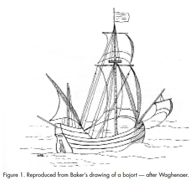
11 A source for understanding the shape and design of sixteenth- century vessels comes from the charts of Lucus Jansz Waghenaer (1533/34–1606), a Dutch mariner and cartographer. Contemporary charts of the Baltic and North Sea commonly were ornamented with drawings of vessels with full rigging that were termed “boyer” by the Dutch and “bojort” by the Swedes.9 Swedish evidence indicates that a “bojort” also was referred to as a “pinnace” (Baker 1962: 73). Drawings by Waghenaer showed interesting examples of “bojorts.” Evident was a flat transom rising from the keel and leading to a high narrow poop, which protruded aft over the rudder (Figure 1). The standing rigging included a main mast at or near midship, a bowsprit with a yard sail, and a short mast with a lateen sail abaft the tiller. The main mast carried a square mainsail with a square topsail.
 Display large image of Figure 1
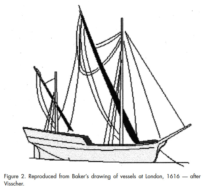
12 Baker’s review of the etchings of the Dutch artist J.C. Visscher notes a scene depicting London in 1616 illustrating a variety of vessels.10 Several of these are of interest, particularly one at anchor that seems to have a raised deck aft and appears similar to Waghenaer’s bojort (Figure 2).
 Display large image of Figure 2
13 The rig consists of a fore-and-aft sprit as a mainsail, a lateen sail placed forward of the tiller, and a bowsprit without any sail. There are three other ships of greater burden that appear to be similar in structure and rig. Each of these has a raised deck aft and is rigged with three masts: a centrally located mainmast, with a square sail and a top square sail on a topmast, a foremast placed near the stem with similar rigging, and a smaller mast just forward of the tiller with a lateen sail. This etching gives an excellent representation of familiar vessels and their rig found in London at the time of Guy’s attempted colonization.
14 Another vessel, the 60-ton Isaac (Figure 3), was drawn by Matthew Baker in 1580 (William Baker 1983: 111). The Isaac was classed as a pinnace because she was a vessel of less than 60 tons that accompanied a larger vessel. William Baker sensibly states that she might also be called a bark.
 Display large image of Figure 3
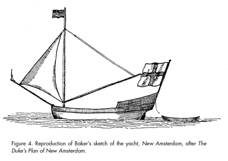
15 Another vessel of interest is the yacht, New Amsterdam, 1661, after J. Franklin Jameson (Figure 4).11 Although the rig is clearly that of a sloop, attention is drawn to the prominent cabin at the stern as a feature of a vessel often referred to as a yacht.
 Display large image of Figure 4
16 The information gathered on the seventeenth-century bark, pinnace, and yacht is the basis used to create a basic image of the likely hull form and rigging of the Indeavour, complemented by some of the construction details of larger contemporary vessels, like the herring buss. At that period, naval architecture was a specialized discipline, but planners were beginning to create designs on paper using a set of rules based on a complicated set of arcs and line intersections. These rules were committed to writing and are preserved in the form of notebooks and manuscripts (Baker 1983). I have developed the shape of the Indeavour based on his analysis of the design of seventeenth-century barks.
Seventeenth-Century Marine Architecture
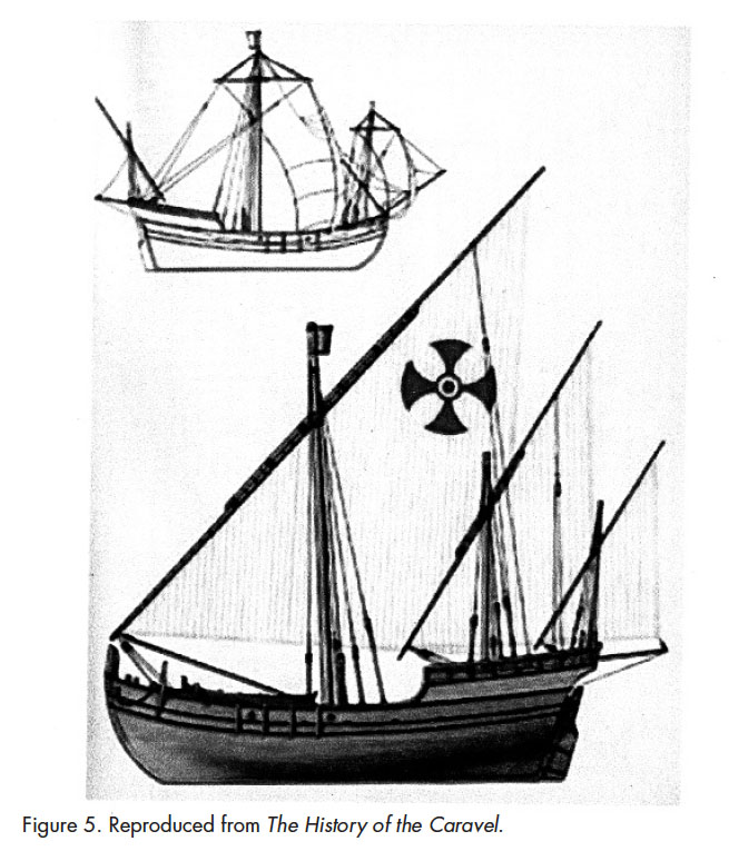
17 The most significant developments in Western European vessel design in the fourteenth and fifteenth centuries occurred in the Iberian Peninsula with the construction of the caravel. These were small vessels developed primarily for fishing, but were decked; thus, they were useful for trading along the Atlantic and Mediterranean coasts.12
18 Caravels are thought to have had a displacement of less than 30 tons, lateen rigged with 1 or 2 masts, originally with a keel-to-beam ratio of 5:1. By the seventeenth century they would have a keel-to-beam ratio of as little as 2.64:1.13 Equally important is the fact that towards the seventeenth century builders began to document procedures for using arcs and tangents for the design of these Iberian caravels.
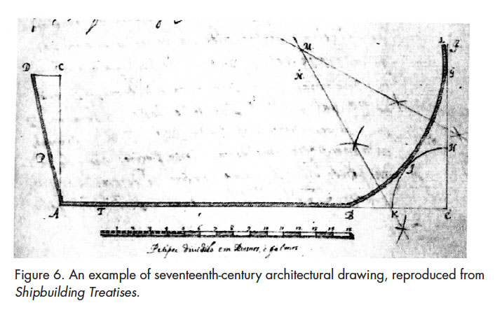 Display large image of Figure 6
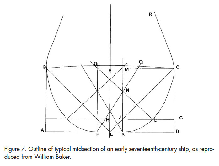
19 Henry VIII saw the advances made in ship construction by the Spanish and the Portuguese and encouraged the immigration of skilled naval architects, particularly as a means of improving ships built for his navy. The architectural rules used in building caravels, and based on geometric arcs and angles, were therefore transferred to the building of English barks and ships. Mathew Baker,14 a master shipwright under Elizabeth I, was responsible for constructing or rebuilding many of the ships that fought the Spanish Armada (1588). Perhaps his most important contribution was documenting the forming of a ship’s rib sections and bow and the forming and location of the mid-ship bend (Baker 1962, 1983). As the naval architect and maritime historian William Baker explains, in reference to Figure 7:
 Display large image of Figure 7
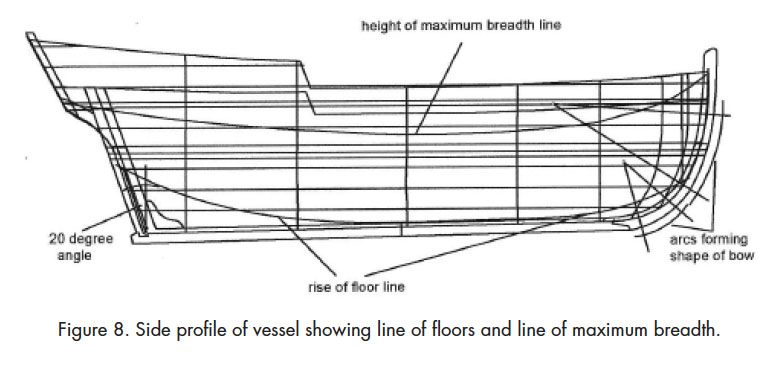
20 The marine architect of the seventeenth century had no concept of “water lines” and “buttock lines” as used today. Instead, the two major lines for reference of the structure of the ribs were the “run of the maximum breadth line” (top line) and the “run of the rise of the floor line”; sometimes these were referred to as the “narrowing and rising lines.” These are illustrated below (Figure 8).
 Display large image of Figure 8
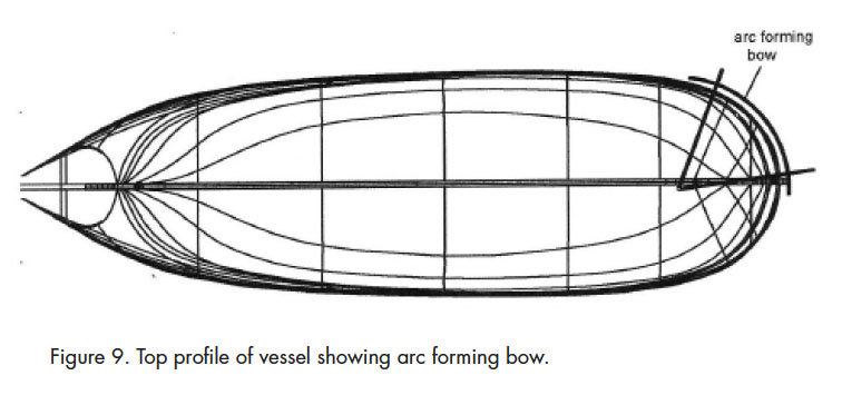
21 Of primary importance is the shape given to the bow (Figure 9). The bow was a rounded tea-cup shape based on an arc with centre just aft the front end of the keel. The bow of vessels remained rounded until well into the eighteenth century (Baker 1962: 24).
22 The stern post is mortised in the end of the keel at an angle of approximately 20 degrees (Figure 10). As a rule of thumb, the length of the vessel beyond the length of the keel — as defined by the rake of the stern post (SP) plus the forward curve of the stem — approximately equals the maximum breadth of the hull (Baker 1962: 13).
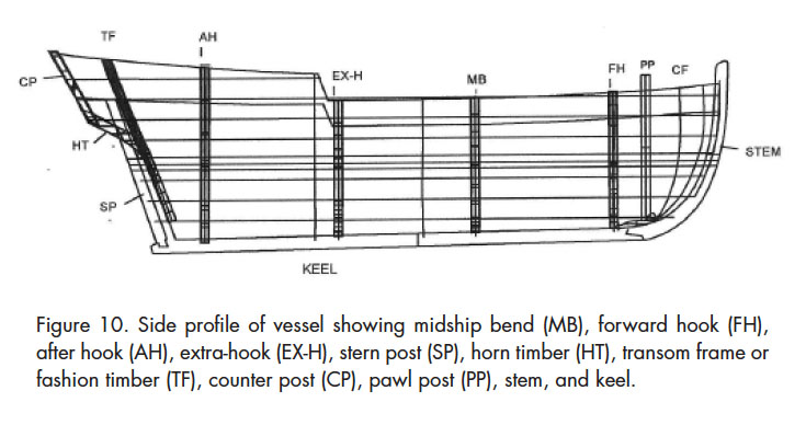 Display large image of Figure 10
Defining the Structure of the Indeavour
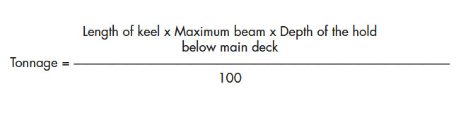
23 The estimation of the size of the Indeavour needs some consideration, given the term “tons burden” and the observation that Guy’s vessel may have been smaller than one might imagine. By 1600, the practice of determining the tonnage of a vessel, and thus port charges and duties on imports and exports based on carrying capacity, was of long standing. The origin of the term “tonnage” dates back to a tax levied by King Edward I in 1303, and a later tax levied by King Edward III in 1377, on each wine container or “tun” arriving by ship. Each tun contained 252 gallons and weighed about 2,240 pounds (1,020 kg). This principle became the basis for taxing all vessels entering a port, so the necessity arose to find a method of estimating the capacity of a ship for the purpose of taxation. The following formula measured in feet was used in England:
24 The essence of this formula is that the hull capacity is estimated, rather than specifying the number of tuns that can be stored in the hold. The above formula was used until 1678 when Thames shipbuilders updated the formula. Upon this basis the dimensions of the Indeavour are calculated. As for the size of the vessel, consideration is given to the fact that the first colonists were ill-equipped for extensive carpentry and they were otherwise occupied with constructing buildings and small open boats.
25 The earlier determination of vessel tonnage from the number of wine tuns an English ship theoretically could stow was replaced by a simple formula related to the vessel’s length, breadth, and depth, given by:

26 Naval architecture of this period calculated the mass burden based on the width of the vessel at maximum beam to outside the planking, depth of cargo hold at midship from atop the keel to under the main deck, and the length as the measurement of that part of the keel spanning from the rudder post to the join at the stem post, and which more specifically represented the “flat lay of the keel on the ground.”
27 The Indeavour was reported to be a bark of 12 tons burden (about 12 tonnes), so the question arising is what dimensions would satisfy the formula for tonnage and at the same time give proportions to a vessel within the boundary of architectural design and stability tolerances of the period.
28 Several practical variations of dimension are to be considered:
29 The Indeavour was a small bark so there are a couple of considerations. First, the relatively small displacement means that it is difficult to maintain headroom in the hold, as a disproportionate amount of freeboard would raise the centre of gravity and create instability. In order to maintain stability the maximum depth in the hold of the Indeavour would of necessity be not more than 6 feet (1.8 m) because of the relatively narrow beam. The crew of the Indeavour, on its historic trip in question, was made up of 12 men, in addition to the master and John Guy, so the accommodations of the vessel below deck must not have been close to standing room. The average height of an English male in the seventeenth century was 5 feet 6 inches (168 cm).15 Furthermore, consideration must be given to the fact that part of the depth of the hold would have been taken up by rock stored above the keel for ballast. The crew were in very close quarters.
30 Given the requirement for standing room below deck, the two most probable variations in dimension from above are (b) and (e):

31 Moreover, when each of the variations is applied to the geometric procedures outlined above; these are the only proportions of breadth to depth that work to produce a hull structure. Consideration is given to stability and practicality when selecting between the two options. Even though the difference in length between the two options is only 2 feet, the difference becomes substantial when applied to the full hull, and the loss of 6 inches in depth effectively lowers the centre of gravity of the hull, making the vessel slightly more stable. A depth in the hold of 5.5 feet and a breadth of 10 feet is closer to the traditional dimensions as the width-to-height ratio of smaller vessels of the period tended be approximately 2 to 1. Two examples of width-to-height ratio would be a collier brig of 1680 with length 70 feet, width 24 feet and depth 12 feet; and a herring buss of 1630 with length of 65 feet, width of 16 feet, and depth of 8 feet. The longer, lower hull would have been more seaworthy and a more likely design for the Indeavour.
32 The hull would have been separated by bulkheads to produce sections for accommodations and cargo storage. According to standard practices, a forward cabin or cuddy forward would have served as crew quarters and chain locker. This area would have been adequate on a routine voyage for a crew of no more than four men. The tradition of living quarters aft had served for centuries as a means of establishing authority and hierarchy on sailing vessels, so it is reasonable to suppose that the Indeavour had quarters in the stern for two persons — John Guy and the captain.
33 The floors of a sailing vessel rise sharply aft, making it necessary to elevate the floor boards of the cabin. To maintain standing room it is necessary to raise the deck aft. A rise in the deck of about 12 inches (30 cm) would be adequate to allow a limited standing room between berths placed port and starboard and the extra space below the floor boards would have been used to store provisions. It was a general practice during the seventeenth century to bring the raised deck aft past the stern post, thus creating a transom overhang. As the transom moved upward and outward, an opening was created along the trailing edge of the stern post through which the rudder shaft would protrude to the deck and be capped with a tiller for steering. Not only did the transom serve to extend the aft quarters, the structure protected the rudder shaft and the helmsman in the case of being “pooped” — i.e., being hit by a wave in a following sea. Ports were sometimes located on the transom to provide light and fresh air in the aft cabin.
34 Beginning with a keel length of 22 feet (6.7 m) and a depth of 5.5 feet (1.68 m), the basic structure of the Indeavour can be established by adding the stem and stern posts. According to the rule already stated, the forward curve of the stem plus the aft rake of the stern post was approximately equal to the maximum breadth. The stem post is then defined by two arcs, and the stern post is rabbeted to the keel with an aforementioned aft rake of about 20 degrees from vertical. Before shaping the major frames, the shipbuilder would have to consider two factors: first, a “rise of floor line” and, second, a “line of height of maximum breadth” (Baker 1962: 24) (Figure 8). A vessel with very low displacement, such as the Indeavour, would have its maximum beam well above the waterline and close to deck level, whereas larger vessels with substantial superstructure would keep their maximum beam low at midship and thus would have a more pronounced tumblehome.
35 At this point in the example, the lines for maximum breadth and floors need only be an estimate to allow the geometric drawing of shapes to represent the midship bend, the fore-hook, the after-hook, and transom. The next operation is to form the shape of the deck from stem to stern. The top profile (Figure 9) of the bow is defined with an arc, and the maximum beam, and thus the midship bend, is placed approximately one-third of the distance aft of the forward end of the keel (Figure 10). The side profile (Figure 8) of the bow is formed by two arcs; the first with centre near the waterline and the other near the level of the deck. A moderate shear is given to the deck as the planking runs fore and aft. As was noted above, the raised after-deck maintains such a breadth as to allow a smooth curve of the gunwale aft.
36 The established practice of building a vessel at the time was to place the frames for the major stations on the keel at location and run battens or flexible laths along them from the transom to the stem post. Each set of ribs was then constructed to fit within the curvature established by these battens and fastened to the keel. The method of geometrically drawing the ribs to form the whole vessel is, in fact, flawed. The method works well along the midship, but becomes flawed towards the bow and stern. In actual practice, this was overcome by the builder adjusting the frames running fore and aft by shaping them with an adze to ensure a smooth curvature to agree with the run of the battens. The use of battens was indispensable because the use of laths to define the shape of the hull defines the hull shape according to the run of the planking. This is important because successive strakes of planks on a hull taper and bend upward away from the keel towards the stem and the stern, and it is essential that each plank run along a defined curve.
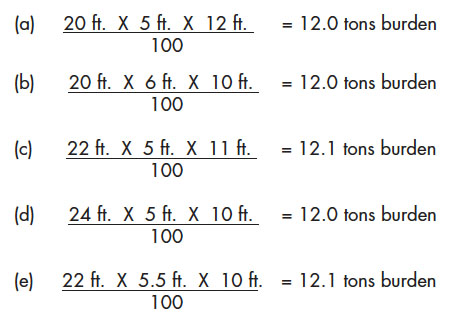
37 The main stations (Figure 11) of the Indeavour can thus be defined by the geometry of seventeenth-century marine architecture. The midship bend of the Indeavour is based on a half-breadth of 5 feet and a depth of 5.5 feet in the hold (1.5 and 1.67 m).
 Display large image of Figure 11
38 It is customary to draw the midship bend (A) first, as it defines the maximum beam and it is more straightforward than the other stations as the floors lay flat to the keel.
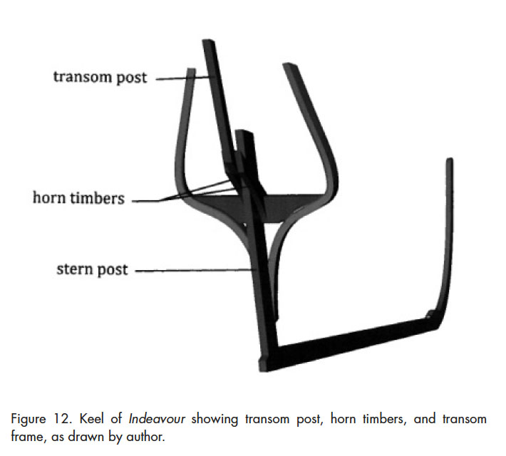
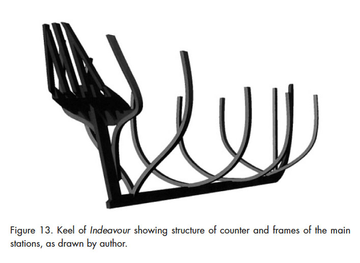
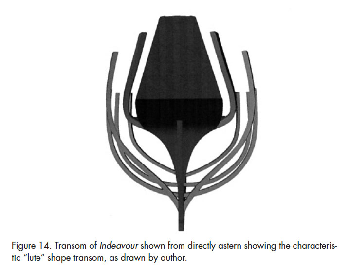
39 The structure of the counter stern needs some elaboration as there are no geometric rules for its structure and shape. The basis of the shape is two horn timbers with a prescribed arc, rising from the stern post and leaving a void through which the top of the rudder protrudes to the deck (Figure 12). The addition of several more such timbers forms the basis of a curved support for the counter. The transom is then formed by frames attached to the end of the horn timbers and rising at an angle approximating the angle of the stern post (Figure 13). The side of the transom is formed by filler blocks cut according to the run of battens along the main frames. The result is a transom, which when viewed directly from astern, resembles the shape of a lute — thus the expression “lute stern” (Figure 14).
 Display large image of Figure 12
 Display large image of Figure 13
 Display large image of Figure 14
40 The structure of the lute stern is quite complex and requires some further explanation. The advantage of this transom is that it carries the breadth of the vessel to the stern as defined by the frame attached to the stern post, i.e., the fashion timber. This type of counter transom allows more spacious accommodations aft, as compared with a double- ender formed when the rabbet of the planking lies along the stern post. In larger vessels the lute stern was ornately decorated, had large ports, and facilitated luxury quarters. This form of stern in the Indeavour, though much smaller, would have the advantage of creating adequate space in the aft cabin for Guy and for the master of the vessel.
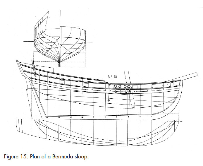
41 The clearest representation of the lute stern structure comes from drawings made by Fredrik Henrik af Chapman (1721–1808) in his eighteenth-century work, Architecture Navalis Mercatoria.16 Although these drawings were made over a century after the Indeavour was constructed, vessel evolution was a slow process and the clarity of these illustrations is useful in demonstrating vessel design in the seventeenth century. Figure 15 shows a Bermuda sloop with overall length of 60 feet. In this illustration the fashion timber runs high with a short counter well above the waterline.
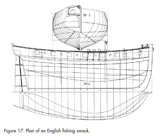
42 This same structure can be seen in an English cutter (Chapman, Plate LX, No. 6) with its overall length of 54 feet and an English fishing smack (Chapman, Plate LIX, No. 3) with an overall length of 38 feet (Figures 16 and 17).
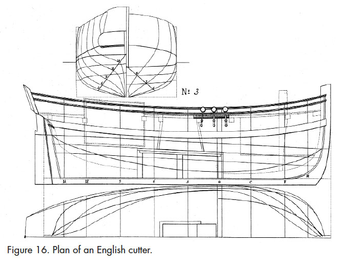
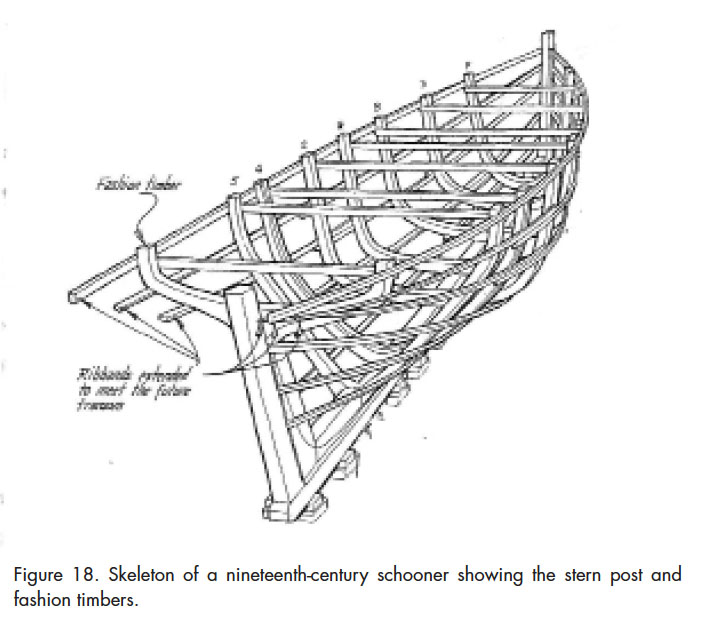
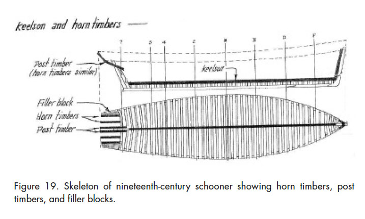
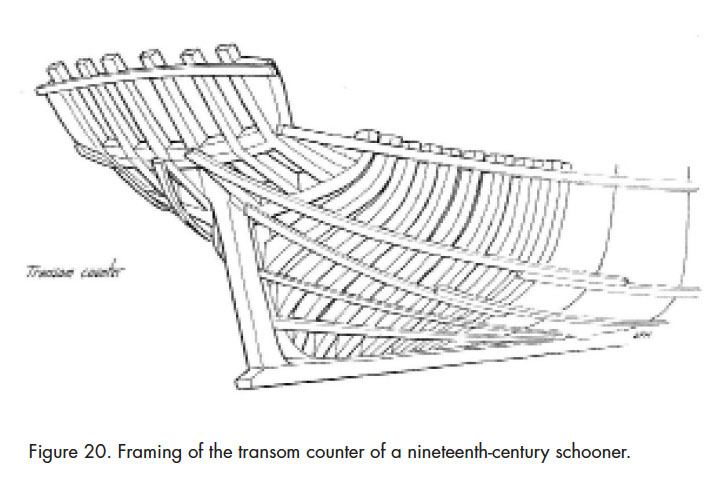
43 Little information is provided by Chapman on the actual joinery used to construct these vessels, though the framing used to form transom counters of later vessels is suggestive. By the nineteenth century the counter of wooden vessels had changed dramatically from that used to build a seventeenth-century bark, but the joinery can give significant insight into the method used to construct earlier vessels. Three illustrations taken from The Evolution of the Wooden Ship by Basil Greenhill give us some insight (Figures 18, 19, 20). The first illustration clearly shows the fashion timber attached to the stern post and ribbands or battens extended to form the transom. The second illustration shows the attachment of post timbers and of similar horn timbers to the fashion timber. Note that the side of the transom is formed by filler blocks. The third illustration shows the completed counter with horn timbers and filler blocks attached to the fashion timber.
 Display large image of Figure 18
 Display large image of Figure 19
 Display large image of Figure 20
44 Details provided by Chapman and Greenhill make it possible to propose the joinery for the transom of the Indeavour. The curved horn timbers form the lower section of the counter stern and transom stanchions are attached to the end of each horn timber. The transom stanchions together with the transom post form the high transom (Figures 12 and 13). As shown in Figures 19 and 20, filler blocks are placed on the outside of the last horn timber and fared with the adze to align with the run of the ribbands. Horizontal planking begins at the lower section of the fashion timber and continues upward to form the concave counter and the straight transom. Planking between the post timbers is omitted to allow passage of the rudder, and an encasement is made around the rudder to form the rudder well.
45 Seventeenth-century paintings provide additional support for the proposed structure for the Indeavour.17 We note the raised poop decks and the high narrow transoms of the vessels in each painting. A vessel painted by Verbeecq is considerably larger than 12 tons, but the intricacy of the afterdeck and stern of vessels of the era is well illustrated. A painting by De Vlieger shows a much smaller craft that seems to be in distress. One can speculate that the painting represents an English vessel since it appears to be off the cliffs of Dover. I have assumed that these images are representative of vessels from the early seventeenth century.
Drawing the Lines of the Indeavour
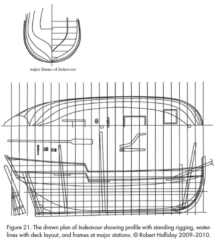
46 The question at hand is: how can a set of plans be drawn for the Indeavour from three stations? The method chosen for doing this is to form a half-hull model using the top profile, the side profile, the shape of the bow, and the shape of the frames at the major stations. The half-hull model, which is composed of “lifts” or layers, is then shaped according to the run of a wooden lath after the manner the master builder would achieve using battens and an adze. After the model is completed, the lifts are separated and the lines are taken from the model and drawn to paper showing profile, waterlines, and transverse frames. Standing rigging and deck layout are drawn, as well as some important fittings such as the rudder and tiller (Figure 21).
 Display large image of Figure 21
47 From this set of plans it is possible to fabricate a full-scale replica of the Indeavour in a accordance with the naval architectural principles of the seventeenth century, and which would represent as closely as possible the vessel built in Cupids in 1610–11 during the first attempt to establish an English colony in Newfoundland.
48 The interior of the vessel would be split into three sections, including the forward crew quarters, the hold at midship that would be used as temporary crew quarters, and the captain’s cabin aft. The length on deck (LOD) or length from end to end of the Indeavour can now be estimated from the profile to be around 33 feet (10 m), so she can be divided into three sections based on an estimate of the space requirements. About 10 feet (3 m) from bulkhead to the stem would be necessary for the forward quarters as that space would need to be adequate for four crew members, a rope locker, and a galley. The size of the cargo hold can be estimated by the requirement for tonnage at approximately 12 feet fore and aft between bulkheads (3.66 m). The remaining length, therefore, would make up the aft cabin and the raised deck.
49 The deck layout is largely defined by the location of the bulkheads, as the cover for the cargo hold would be centred to the hold. A wind-lass would be placed, by necessity, aft of the pawl post so the entrance to the forecastle would be offset, traditionally, to the starboard side. The entrance to the aft cabin, by nature of the cabin shape and layout, would be located centrally.
50 A key consideration is the height of the bulwarks. Based on the statement that the Indeavour was a vessel “to sail and row about the headlands” and giving regard to her overall size and displacement, it is most likely that she had six rowing stations with oars about 14 feet long (4.27 m). The need, at times, to row may explain the relatively large crew of 12 men on the historic voyage to Trinity Bay in 1612. The vessel was decked, which would require the crew to row from a standing position. The height of the bulwarks can be estimated based on the height of purchase needed to support a 14-foot oar between a man’s chest and the water. If the waterline is estimated to be 2.5 ft. below the gunwale (0.76 m) and the half breadth of the deck is 5.5 feet (1.68 m), the purchase and thus the bulwarks would need to be about 18 to 20 inches high (about 50 cm). The bulwarks would be solid, as opposed to spindle railing, in order to withstand the force of three oars on each side pulling forward in unison. The bulwarks would be supported by evenly spaced stanchions from stem to stern extending above the gunwale. The bulwarks aft on the rise deck would become more elevated, as depicted in many drawings, towards the transom to provide further protection for the helmsman. The planking used for the bulwarks would be thinner than the hull planking and there would be a space at the bottom of the bulwarks (scuppers) to allow water to run off the deck.
51 The rig of the Indeavour is open to speculation. A popular rig on vessels in the range of 30 to 40 feet (10 m or so) was the hoy rig or hoy plus a lateen sail. The hoy rig generally had a single mast with a lugrigged sail (a four-sided fore-and-aft sail supported by a yard and similar to a gaff sail.18 However, there is adequate evidence of the rigging of barks during the early 1600s to permit decisions on the rig. William Baker reported that a group of ship carpenters and ship masters in 1590 appraised the 35-ton bark Katheryn of Weymouth and the survey reported that she “carried the normal three-masted ship rig of that period — fore, main, and mizzen masts with topmasts on her fore and main” (Baker 1962: 81–82). Baker believes that, in general, the small and medium-sized barks had a two-mast square rig and did not carry the mizzen sail; however, it was standard practice to carry a lateen sail on a mizzen mast on the quarterdeck. I believe it was likely that the Indeavour would have carried a lateen sail so that the vessel would be balanced on a reach, and particularly when the wind increased to the point where the main sail was lowered. The mizzen sail also would be useful to keep the boat steady when the crew was rowing. The Indeavour, having a light displacement, would have had difficulty carrying a top-sail, so I have not added a topmast. There may have been a masthead flag staff carried on the main.
52 As for placement of the masts, it was accepted practice to station the main mast just aft of midships and abaft of the cargo hole. The fore mast would be placed close to the bow ahead of the windlass. This mast is stepped at the foot of the pawl post, thus giving the mast a noticeable rake forward. The short mast of the lateen sail is placed on the raised deck just forward of the tiller and the heel of the lateen sail would be tacked at the base of the main mast. An equally acceptable arrangement, which can be observed in some drawings, would be to have the short mast placed foward of the tiller and a boom extending from the transom to hold the sheet lead (Figure 1).
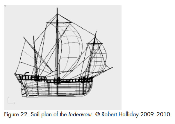
53 A bowsprit supports the standing rigging via a guy led aloft to the top section of the fore mast and to serve as a tack for the two fore-guy blocks for the yard of the foresail. The bowsprit would have been fastened to the deck beside the pawl post to exit towards the top of the bulwarks, lashed to the stem post, traditionally on the starboard side. No jib is attached to the bowsprit as it is believed that sails were not fastened in this manner until late in the seventeenth century, although a small square sail may have been set under the bowsprit (Baker 1962: 5) (Figure 1). The standing rigging (Figure 22) was quite standard for all vessels of that period and would consist of three shrouds on the main mast and one or two shrouds on the foremast, each attached by a double deadeye. The yard on each mast is hoisted by a single halyard and a series of blocks are used to run topping lifts and guys to control the yards, and to run sheets to control the sail.
 Display large image of Figure 22
Conclusion
54 Although no half-hull models of the Indeavour exist, and little to no information regarding the vessel’s fate is available, information gleaned from historical sources and records of seventeenth-century shipbuilding can be used to approximate the construction of a small-decked vessel of the period. Taking into account the general historical information available and pairing it with accounts of the particular vessel and its own history, the plausible model of the Indeavour proposed here conforms to the dimensions and style of the period.