Ships and Shipbuilding / Navires et Construction Navale
The Amsler Integrator and the Burden of Calculation
Abstract
British naval architects of the eighteenth and nineteenth centuries are often accused of failing to take a scientific approach to shipbuilding. This article explains this "failure" through an investigation of the context and culture of ship design practice, focusing on the relationship between plan drawing, scientific calculation and the advent of the Amsler Integrator. Measured plans drawings made predictive calculations possible. But calculations were so extremely long and tedious for so little gain that they were very rarely made. The Amsler Integrator promised to relieve designers of this "burden." A form of mechanical computer introduced in the 1880s, the integrator dramatically reduced the time it took to calculate a ship's stability and thus promised to make the application of science to shipbuilding a practical possibility.
Résumé
On accuse souvent les architectes navals britanniques des XVIIIe et XIXe siècles de ne pas avoir adopté d'approche scientifique à la construction des bâtiments maritimes. L'article que voici explique cette « omission » en menant enquête sur le cadre et la culture des méthodes de conception navale. Il s'attarde notamment aux liens entre la production de plans, le calcul scientifique et l'avènement de l'intégrateur d'Amsler. La production de dessins avec mesures a permis d'effectuer des prévisions. Néanmoins, ces calculs longs et fastidieux apportaient si peu qu 'on y recourait rarement. L'intégrateur d'Amsler promettait de soulager les concepteurs de ce « fardeau ». Sorte d'ordinateur mécanique introduit dans les années 1880, cet appareil a diminué de beaucoup le temps qu'il fallait pour calculer la stabilité d'un navire et rendu possible l'application des principes scientifiques à la construction navale.
1 A recent display at the Massachusetts Institute of Technology included a nicely symbolic arrangement of two artifacts from the Hart Nautical Collection. On the bottom of the display case was a body plan showing multiple cross-sections of a merchant steamer from the 1890s. On top of the plan was an Amsler integrator, a mechanical instrument capable of calculating the areas and moments of the cross-sections in the drawing, which in turn allowed a calculation of the vessel's curve of stability. Nowadays, as a form of mechanical computer, the integrator looks rather quaint. At the time the instrument was introduced it was hailed as one of the greatest developments in nineteenth century naval science.
2 This article seeks to unpack the reasons for this claim as a way of investigating a story about science in British shipbuilding that those interested in ship design will often have encountered. Frederick Robertson gave classic expression to it in his This Evolution of Naval Armament of 1921, describing the supposed lack of science in British naval architecture as the "greatest blunder of two centuries," leaving ship design in the hands of craftsmen who could do no more than "grope" their way forward on the basis of "blind lore" and "dogma," held back by "hereditary principles" and "cautious timidity." More recently, historian Stanley Sandler has written of the craft "rule-of-thumb system that had served the Royal Navy so badly." Historian of science A. Rupert Hall has argued that French investigations of ship stability and resistance were ignored by British shipwrights because of the "anti-theoretical conservatism of British shipyards." Similarly Pollard and Robertson, in their extremely influential work on nineteenth-century British shipbuilding, have faulted British shipbuilders for failing to adopt scientific methods, connecting this failure to the ultimate decline of the British shipbuilding industry in the twentieth century.1
3 Most accounts of this sort revolve around the assumption that because we now employ scientific theory on an immense scale in design, it must have been useful in the past, and therefore those who failed to take a scientific approach are to be regarded as at best craftsmen, and at worst conservative laggards. What most commentators have not done, however, is stand in the shoes of earlier ship designers and ask themselves if there might not have been a real problem.
4 By investigating the significance of both measured ships' plans and the Amsler integrator, in this paper I hope to show that nineteenth-century naval architects faced very real difficulties in trying to apply scientific theory to ship design. My overall strategy is contextual and it will be necessary to take a long view. I begin by showing how and why measured plans came to be the central instruments of design in naval architecture and the essential foundation for the application of quantitative scientific theory to the design of individual vessels. Next, focusing on the theory of stability, I show how the attempt to apply mathematical physical theory to a ship's plan was hampered by the complex of problems I refer to collectively as the "burden of calculation." One part of this burden was that calculations of stability were extraordinarily long and complex but offered surprisingly little guidance to the designer. A second part was that, because the calculations were so long and complex, they required the employment of an expensive, mathematically-trained professional staff, and this necessity ran directly counter to the demands for economy in the drawing office.
5 As we shall see, nineteenth century naval architects regarded the Amsler integrator as a tremendous breakthrough precisely because it promised to solve both these problems, simplifying calculations of stability to the point that they could be carried out by apprentice boys and girls instead of expensive professionals. On this basis, they believed the integrator would open a new era in the scientific approach to naval architecture by permitting the practical application of scientific theory to merchant shipbuilding for the first time.
Drawing and Design
6 To begin establishing a context for the Amsler integrator, it will be important to explain two fundamental features of wooden ship design in the period 1800-1870. The first is the crucial role of measured plan drawings in warship design and construction, but not merchant building. The second, discussed in the following section, is the tremendous degree of uncertainty about the behavior of ships that dogged innovations in hull forms.2
 Display large image of Figure 1
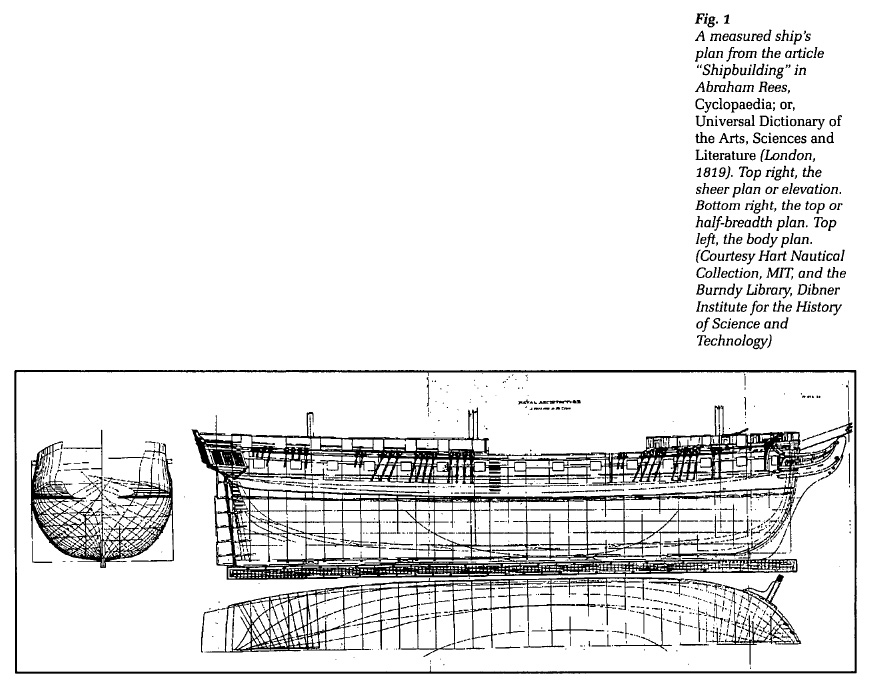
7 Figure 1 shows the kind of plans in use in naval architecture around 1800, as illustrated in the Encyclopaedia Britannica.3 Above right is the side elevation or "sheer plan." Below the line of the keel in the side view is the top or "half-breadth" plan which, because ships are symmetrical around their axis, shows only half the vessel. In the upper left is the "body plan," showing multiple cross-sections of the hull at regular intervals along its length. The outside lines of the body plan represent the widest point of the vessel's hull. The lines to the right and left of centre represent multiple cross-sections tapering towards the stem and stern. Each line also represents the shape of an actual frame whose location along the keel is shown by the straight, perpendicular lines in the other two drawings. Importantly, the three views constitute measured plans, a fact indicated by the scale found at the bottom of each drawing.
8 As might be obvious, these plans determined the overall form of a ship's hull. But it is not so obvious that they also contained the information necessary to determine the dimensions of all the thousands of timbers, beams, knees, frames, etc., out of which the hull was built. The dimensions of these parts were derived from the plans in the dockyard, where parts of the drawings were first laid out at full-scale on the "mould loft" floor. Then extremely complicated geometrical procedures were applied to derive the dimensions of individual parts as necessary.4 Templates were made to fit the full-scale manipulations and issued to the dockyard workers, whose task was to cut the timbers exactly to match.
9 The plans shown in Figure 1 were the result of two centuries of refinement of a representational technique originally introduced by English Master Shipwright Matthew Baker circa 1586.5 The date is significant because it was during the time of Elizabeth that the introduction of shipboard cannon made it necessary for the state to bear the enormous expense of a permanent fleet and a permanent dockyard establishment. As is well known, Elizabeth and her successors were chronically short of funds. This indicates that the appeal of Baker's methods lay in the fact that they promised a great savings in warship construction.6
10 How the use of plans led to economy can be understood by imagining the "craft" construction of a warship without the use of detailed drawings and templates, in which case the thousands of pieces that made up a hull had to be individually cut and shaped until they all fit together. This kind of cutting and fitting is inherently wasteful of materials, since each part must start out oversize and then be reduced to fit. Cutting and fitting is also inherently time consuming because of the care with which the parts must be gradually adjusted to each other. Moreover, the process is labour-intensive because of the high level of skill with which the shaping of parts must be carried out in order to avoid excessive waste. In other words, building warships by craft methods is inherendy expensive. By contrast, the use of plan drawings allows a specification of the dimensions of parts in advance of fabrication. Specifying dimensions in advance allows a reduction in the waste of materials. It also allows a division of labour in which different pieces of a ship can be made by different people yet still fit together. In turn this division of labour allows an increase in the rate of production, since parts that would take a single craftsman several days to make can be made at the same time. In short, the use of plans leads to savings in time, labour and materials.
11 Recognizing that plan drawings were originally employed to save money in construction is important because it points to a feature of ship design that is often overlooked, namely the all-pervasive influence of costs and the continual demand for economy. It also helps to explain a mystery in early modern naval architecture, which is that measured plans were used only in the construction of British warships after 1600, and almost never in the building of wooden merchant vessels. Eschewing all talk of "dogma" or "conservatism," the explanation for this must surely be that merchant shipbuilders found their own techniques to be entirely adequate for their purposes — the making of money. This being so, there was no reason for them to invest in the design overhead required by the use of plans, meaning the maintenance of a permanent drawing office and the employment of expensive persons with the necessary drafting and mathematical skills. That is, if the reasons for the introduction of plans in the building of warships was to save money in construction in a context of high costs to the state, it seems that the context of costs and profits in merchant building simply did not necessitate a shift to the more elaborate, expensive and time-consuming methods of design used at the Admiralty.
12 As we shall see, the pressure on commercial shipbuilders to keep design overheads low continued far into the nineteenth century and had an important effect on the application of science.
Design and Uncertainty
13 Recognizing that plan drawings were originally introduced to reduce the cost of constructing warships is also important because it points to the fact that ships' plans were fundamentally oriented towards problems of deriving the dimensions of parts and not to problems in the design of hull-forms. Most significantly, they failed to provide a means for overcoming the biggest problem in ship design, which was that each new design involved tremendous uncertainties about the behavior of the resulting ship at sea. As it is directly related to the question of science in shipbuilding, a brief explanation of the reasons for this uncertainty will be of value.
14 The place to begin is with the observation that warship designers in the age of wood had a very consistent list of the qualities desired in a sailing warship, according to which a good ship should sail well, sail into the wind, make little leeway, possess adequate stability, pitch moderately, and carry its guns high enough out of the water that they could be used in any weather.7 Early naval architects were also well-aware of the hull shapes needed to secure these advantages. They knew, for example, that fine lines aft gave better steering, that narrow ships with sharp entrances had greater speed, that greater breadth gave greater stability, a greater capacity to carry sail, and so on. But crucially, these designers knew that the dimensions required to achieve the various desirable qualities conflict with each other in an extremely complicated manner and that there was no way to combine all the desirable qualities in a single hull.8
15 As John Knowles explained in his influential treatise on naval architecture of 1822:
16 But as Knowles emphatically concluded: "to unite, in one ship, all these desirable qualities, some of which are subversive of others, is impossible."10
17 The conflict between the qualities meant that naval architects had to choose which of the qualities they most desired and which they could sacrifice. This choice could only be made on the basis of the purpose of the vessel in question. Thus as Knowles explained, the first object in designing a ship was to "consider the various purposes that it is intended for, and the various impediments that it may meet with. " For only in light of the purpose could the ship be given the "arrangement of its parts and combination of its principles; especially where it will be necessary that contradictory powers shall be blended together."11
18 Every ship was thus a compromise. There was something "wrong" with each of them. But how wrong? Here the problem was the dimensions governing the various qualities interacted with each other in such an extremely complicated fashion that early warship designers had no way of knowing precisely how obtaining one quality would affect the others. For example, a designer might change the lines of his plans to increase the beam of his vessel in an effort to increase carrying capacity. But he had no way of knowing precisely how this would affect speed, leeway or stability. Worse still, it turned out that even small departures from a previously successful design could ruin the performance of a new ship at sea. Indeed, one of the most frequently repeated stories in early modern naval architecture concerns sister ships, built to exactly the same plan, which had radically different sailing properties — one good, the other bad. The purpose of such stories was to stress the fact that even apparently trivial variations in design could result in such inexplicably large changes of behavior as to "wholly change the qualities of a ship from bad to good, or the reverse."12
19 Given that they were building extremely costly vessels, carrying as many as eight hundred men, where failure might have dire consequences for the'state, this kind of uncertainty placed naval architects in the position of having to innovate in a context of enormous risks. Given these risks, it is not surprising that they often stuck as closely as possible to previous designs that were known to perform well. But by the same token, some means of predicting the future behavior of paper designs became highly desirable. And it is just here that the use of plan drawings presented an intriguing possibility — namely, the possibility of using mathematical physical theory to predict the future behavior of vessels at sea, and thereby eliminate uncertainty in ship design.
Ships, Science and Burden of Calculation
20 In turning to the discussion of the relationship between science and early ship design we are already in position to lay down two fundamental principles. The first may be stated as drawings first, then science. For if one stops to think about it, without the use of measured plans in design there could be nothing to quantify and so no possible application of mathematical physical theory whatsoever. Moreover, without the use of measured plans to achieve accuracy in construction, there could be no point in applying scientific theory in design, since there could be no point in calculating the behavior of a "paper" ship if the real ship was going to be built and behave differ-endy — certainly not when it is known that small alterations in design can produce large changes in a vessel's various qualities.
21 The second principle is that what can't get into the drawings can't get into the ship, and this provides definite criteria for investigating the use of science in early naval architecture, for to be of any real benefit, the use of physical theory had to be capable of having some effect on the drawings, or else it would be largely irrelevant to the design of actual ships.
 Display large image of Figure 2
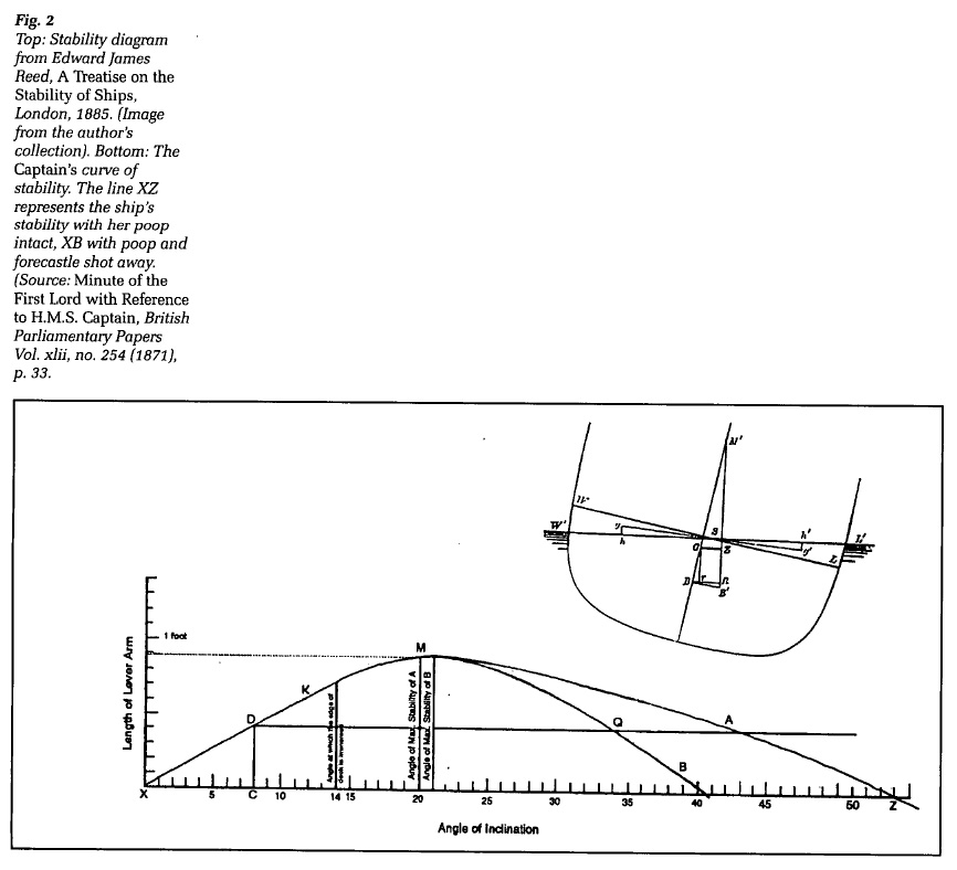
22 Alas, this second possibility was closer to the truth. To see why, it will be necessary to undertake a brief discussion of the theory of ship stability, the basic principles of which may be easily grasped with the aid of the diagram in Figure 2 (top).
23 In essence, the theory of stability concerns the relationship between two mathematical points. One is the centre of gravity G, representing the centre of the weight of the hull of a ship and all that it carries, through which the force of gravity is considered to work down. The other is the centre of buoyancy B, representing the centre of gravity of the water displaced by the hull, through which the force of buoyancy works up. In the upright position of equuibrium, with the waterline at WL, these points are directly above each other in the centre line. But when a ship is inclined, the centre of buoyancy moves away from the centre line to B' (as a result of the changing shape of the immersed part of me hull under the new waterline WL'). A "righting couple" is then formed by the force of gravity working down through G and the force of buoyancy working up through B, the leverage of which is proportional to the lever arm GZ. The amount of righting force tending to return the ship to its upright position is found by multiplying the length of GZ by the weight of the ship.
24 Another important point to consider in the diagram is the theoretical point M'. This is the "metacentre" and represents the point at which the vertical line of the force of buoyancy working up through B' in the inclined position crosses the original centre line GB. The point has a double significance. In principle, the greater the height of the metacentre above G, the longer the lever GZ will be and the greater the righting force possessed by the ship. Secondly, it will be clear that as the ship inclines further, B' will change position and consequently so will M'. As long as M never passes below G, or G beyond M', there will always be some righting force. But if the metacentre ever passes below the centre of gravity, then it would also pass to the right of the centre of buoyancy B', forming a couple that will act to turn the ship over. In most cases, the higher M is above G, the less likely this is to occur. Thus a ship's stability was often expressed in terms of its "metacentric height," meaning the height of the metacentre above the centre of gravity.
25 The basic principles of stability were originally put forward by French theorist Pierre Bouguer in 1746 and subsequently elaborated by such luminaries as Daniel Bernoulli and Leonhard Euler. These theorists often concerned themselves with the issue of metacentric height.13 In 1796 and 1798, however, Englishman George Atwood presented two papers on stability to the Royal Society of London showing that although vessels of different form could have the same metacentric height at an initial angle of heel, one might possess no righting force whatever at a larger angle and would consequently capsize.14 Since metacentric height was not always a safe guide, Atwood worked out detailed methods of determining actual righting forces.15
26 By 1800, the situation was thus that the theory of stability had been put on a more or less sound basis and that methods of calculating the stability of actual ships had been established. Moreover, one can easily imagine the potential importance of calculating stability in the design of a sailing vessel, because the designer could, at least in principle, discover if his ship possessed the righting force necessary to resist the attempt of the wind in the sails to turn the vessel over.
27 And yet, as commentators universally agree, between 1800 and 1860, stability calculations were almost never carried out in the design of actual ships. Now, this is easily explained in the case of wooden merchant vessels. Plans were not used in the design of merchant ships. Consequently, stability calculations could not be made. But why weren't stability calculations carried out for warships, where plans were used, and where costs and risks were extremely high? Answering this question can bring us to an initial appreciation of the problems I refer to as the burden of calculation.
28 The first problem was that the calculations necessary for determining stability at even a single angle of heel were extremely complicated, immensely tedious and extraordinarily time-consuming. To determine the longitudinal position of the centre of gravity one had to divide the area of the waterline (represented in the half-breadth plan) into several sections of equal length, carefully measure the areas and moments of each of the sections in relation to a known reference line, then combine the results mathematically. To determine the vertical height of the centre of buoyancy one had to repeat the procedure, this time working from a sheer plan divided into layers of equal height by successive waterlines. Finding the height of the centre of gravity was extremely tedious, because it required the calculation of the weight and centres of gravity of every single timber of the hull and every single thing to be carried on board — ballast, guns, stores, men, masts and so. These centres then had to be plotted with respect to a known reference point before they could be summed up. Once the centres of buoyancy and gravity were located, the position of a new centre of buoyancy at some fixed angle of heel still had to be found, an operation carried out on a diagram of the cross section of the ship at the location of the centres of gravity.
29 Any more detailed discussion of stability calculations would be out of place here. Suffice it to say that according to one estimate it could take two years to calculate the stability of a vessel at a single angle of inclination using the methods available as late as I860.16 Entire ships could be built faster than this.
30 If one element of the burden of calculation was thus the immense amount of time it took to calculate anything, a second was that the results gave almost no guidance to the designer on how to change his plans to correct difficulties. This may already be obvious from the fact that a knowledge of righting forces at one angle of heel did not necessarily say much about righting forces at other inclinations. However, the analysis can be pushed farther. Say, for example, the designer believes his centre of gravity is too high and needs to be lowered. But the location of the centre of gravity is an extraordinarily complex matter determined by the distribution of weights throughout the ship, so which lines in the plans should be changed to move it, and how much should they be changed? Knowing the initial position of the centre of gravity says almost nothing about this. Similarly, the designer may not like the position of the centres of buoyancy. These are determined in an extremely complex manner by the overall form of the hull. Which lines in the plans should he move to change the form? Should the height of the sides be increased? Should the breadth be made larger or smaller? Where? In the middle portion of the hull? All along its length? And by how much should the lines be moved?
31 In fact the decision on which lines to alter and how much to alter them could only be made on the basis of the judgment of the designer, acting in light of the purpose of the vessel. But how could a designer then be certain that the changes made actually gave the results desired? In principle, the only way to be certain was to re-draw the plans, re-calculate the weight of the ship, the positions of centre of gravity and buoyancy and so on. That is to say, achieving certainty though the use of quantitative theory required the use of feedback loops of drawing, calculating and redrawing into the design process. If initial calculations were tedious and time consuming, subsequent loops added immensely to the tedium and delay. But, supposing that further problems were identified, the designer was then right back where he started, faced with the ugly prospect of redrawing his plans and re-calculating all over again. Finally, it might be noted that even if a designer was crazy enough to complete several tedious feedback loops, this did little to achieve the overall goal of reducing uncertainty, not just because the designer would sooner or later have to stop calculating and trust his judgment, but because the designer adjusting lines to move centres of gravity and buoyancy was simultaneously altering the dimensions that governed all the other sailing qualities. In this way the attempt to reduce uncertainty about displacement actually introduced uncertainties about the ship's other properties.
32 The picture that emerges is that prior to 1860 calculations of stability involved an enormous expenditure of time and energy for a very little benefit. But there was an additional problem that needs to be noticed. Calculations of stability required the employment of naval architects who were highly trained in mathematics and physics. Such persons commanded good salaries. But the ultimate objective of design in naval architecture was to reduce the costs of construction. Taking on the extra naval architects needed for lengthy calculations ran directly counter to the desire to maintain as small and economical a design staff as possible.
33 This reluctance to carry the overhead of a large design department can clearly be seen in staffing levels at the Admiralty. There, the high cost of warships meant that many different kinds of calculations were carried out. Indeed, the Admiralty established various schools to provide a supply of designers with the necessary mathematical skills.17 But considering that there might be dozens of ships building at any given time, numerous designs in hand and endless calculations to make, the design staff of the navy was extraordinarily small. In 1833, for example, there was only two official members of the Surveyor's Department. By 1860, the design staff at the Admiralty consisted of only eight souls: one surveyor, two assistants to the controller and five draughtsmen.18 There simply weren't enough bodies available to carry out lengthy stability calculations. Moreover, there was little point in adding bodies as long as the results gave so little guidance to designers in changing the lines of their plans.
34 After 1860, there were two significant developments that need to be noted. The first took place in 1861, when Admiralty constructor Frederick Barnes devised ways to shorten calculations of stability (although it is important to stress that Barnes's methods were still far from brief).19 The second development was graphical and involved no really new principles. It took place in 1867-68 when Admiralty constructors devised the calculation of curves of stability like the one in Figure 2 (bottom).
35 What this curve represents can be understood by returning to the image at the top of Figgure 2. There we saw that the righting force tending to turn a ship back to the upright position is proportional to the lever arm GZ, whose length is determined by the position of the centre of gravity and the centre of buoyancy B'. As the ship inclines, the centre of buoyancy moves, and the length of GZ varies accordingly. What Barnes's method allowed for the first time was the practical possibility of calculating successive positions of B' and thus successive lengths of GZ. It is the successive lengths of the lever arm GZ that are plotted against the angle of inclination in the graph in Figure 2 (bottom).
36 It will immediately be apparent that such a curve contains a mass of useful information when compared to a simple knowledge of meta-centric height, or of righting forces at a single inclination. For example, the curve indicates the point at which all righting force vanishes, something which had never been calculated before. It also shows the maximum point of stability, after which a ship suffers a declining ability to right itself. In this case the maximum occurs at only twenty-one degrees. Such information allowed the designer to consider whether this was really safe, since the force of the winds might often push a sailing ship past this point. If the force of the wind steadily exceeded the maximum the ship would simply continue to turn over. Nothing could stop it. At the same time, a curve like this could tell the commander of such a ship when his vessel was in danger and allow him to take remedial action.20
37 Here was a useful tool. And yet, even Admiralty constructors did not immediately make the calculation of curves a matter of course. That this is so may be illustrated by explaining that curves of stability were originally devised in 1867 in the context of a bitter public dispute over proposals to build ocean-going "monitors," with main decks only four feet out of the water, but carrying a full spread of sails. Believing such vessels were dangerous, Chief Constructor of the Navy Edward Reed ordered his staff to use Barnes's methods to calculate the righting ability of such vessels at succeeding angles of inclination. The resulting curves were presented in public in 1868 and showed how ridiculously unsafe these monitors would be.21 The proposal died. At the very same time, however, the Captain (designed by half pay naval officer Cowper Coles) was already being built. The only difference between this ship and the monitors was that the Captain's main deck was to be eight feet out of the water. It was therefore clear that this ship might also be unsafe. Not only did the Admiralty constructors fail to calculate curves for the their own low-decked designs, they failed to calculate curves for the Captain until 1870, when the ship was already built and, in fact, at sea on a trial cruise. Examining the curve, Admiralty constructors predicted that the ship could capsize in certain circumstances. A few days later, on September 7, 1870, the Captain capsized under precisely those conditions with gruesome loss of life.
38 That Admiralty constructors failed to make use of their own curves of stability in the years 1867 to 1870 is explained by the burden of calculation. First, although Barnes's new methods reduced the time needed to calculate stability at single angles of heel, this was to a certain extent countered by having to calculate multiple positions of the centre of buoyancy in the construction of a curve. Unfortunately, I have not been able to find any direct statement of the time required. In the case of the Captain, inclining experiments on the completed ship were carried out to determine the initial position of the centre of gravity, thereby eliminating the most tedious and time-consuming chore. Even so, it took two men one month to complete her curve. Secondly, though curves might reveal gross errors, they provided no more guidance on how to change the lines of plans than older calculations. Thirdly, there were only fourteen members on the Admiralty design staff at this time. They were so busy with their other responsibilities that, except in unusual circumstances like those surrounding the Captain, they had no time to make lengthy calculations for so little guidance.
39 It was only after the sinking of the Captain in 1870 that the calculation of curves of stability for warships became the norm.22 We may note how late this is, considering that the basic principles of stability had been known for the better part of a century.
Stability and the Cargo Steamer
40 So far we have focused on the relationship between drawing and science in the design of naval vessels. The reason for this is that measured plans drawings were not employed in commercial practice for most of the period 1600 to 1870. Hence science could only be applied to the design of warships. This situation only began to change with introduction of the use of plans in the construction of iron steamers in the early nineteenth century. Then came the beginnings of the "shipping revolution" in the years 1860 to 1880, when metal, steam-powered cargo vessels finally proved themselves to be cheaper and more profitable to operate than wooden sailing ships. Metal ships began to take over the world's carrying trade.23 This had such a dramatic effect on British shipbuilding that by 1881, of the 690 000 tons of the merchant shipping building in Britain, only 30 000 tons still represented wooden vessels.24
41 The shift is important because metal shipbuilders had to order such things as plates, brackets, and frames from iron and steel mills. To do so they had to have some way of specifying the shape of parts in advance. It was thus in the first decades of the shipping revolution that the use of measured drawings became an established part of commercial shipbuilding practice and the two pre-conditions for the application of science to merchant vessels were finally in place. That is, merchant shipbuilders were making extensive use of the kind of quantitative representations needed for the application of physical theory. And they were using plans to build ships accurately, meaning that completed ships closely resembled their "paper" originals, giving calculations a potential relevance. Naturally, as more and more metal cargo steamers were built, more and more were lost at sea. Many of these losses were traced to problems with stability. Ensuring adequate stability came to be recognized as a central design problem.25
42 The situation in the 1870s was thus that measured plans were in use, stability had been identified as a major issue, and methods of calculation had been established. As Admiralty constructors William White and William John commented in 1871, "naval architects had simply to decide whether or not it was worth the trouble to perform an elaborate calculation in order to ascertain the variations in the stability of any ship designed by them."26 The fact is, however, that commercial builders believed it was too much trouble. Calculations of stability in the design of merchant steamers were rarely made. To finish setting the stage for the Amsler integrator, this needs to be explained. Explanation requires closer attention to the kind of problem that the stability of steamers represented.
43 A key point is that the conditions of stability in cargo ships are very different from those found in naval vessels. This is because a high proportion of the heavy weights to be carried in a warship — iron plates plating, beams, bulkheads, guns, armour, and the like — are of a fixed and permanent character, while the proportion of movable or consumable weights is small. Accordingly, a warship on a cruise might use up hundreds or thousands of tons of coal but this was a only small fraction of the total weight of the ship and therefore did not dramatically affect the position of the centre of gravity. The stability of a warship was thus determined within limits of a very narrow kind.27 Accordingly, by 1880 it was considered sufficient to calculate curves for three conditions: fully laden; fully laden with coals consumed; and light, with all coals, ammunition, and consumable stores expended.28
44 The conditions of stability in cargo ships was radically different because the permanent weight of a steamer's hull was only a small proportion of the consumable and movable weights. In many cases, the weight of the hull was only a third of the total weight of coal, stores, and cargo. Unlike a warship, therefore, a cargo vessel on a voyage would use up large amounts of coal. The consumption of this weight would by itself seriously affect the position of the centre of gravity, and so the ship's stability. Many ships were thought to have been lost for this reason alone. But in addition, the ordinary merchant vessel was required to carry cargoes of such different density as, on the one hand, pig-iron or steel rails, and on the other, cotton or tea. Merchants ships were thus liable, and likely, to be sent to sea at any draught between the extreme light and maximum load conditions. Their stability varied accordingly, then varied continuously as coals were consumed.29
45 The point is that conditions of stability in a cargo vessel were actually much more complex than those of a warship. Accordingly, it was considered desirable that curves be calculated for at least five conditions: the launch condition; finished but without cargo, coals or stores; fully loaded with coals, stores and cargo; fully loaded with coals consumed; and half loaded with coals consumed.30 That five curves might be needed brings us directly back to the burden of calculation. It will be useful, however, to separate the issues into two problems, one being the problem of design, the other the problem of operation.
46 In design, the main job of the naval architect was to draw up the plans of a ship so that it could be built. The initial purpose of scientific calculations was to predict the future behavior of the ship so the plans could be corrected if necessary. Calculating one curve was a lengthy and tedious task. Calculating five represented an enormous effort. But, as before, the quantitative results did not tell the designer precisely where and how to change his plans in order to correct a difficulty. If it was thought that the centre of gravity was too high, the designer might well try to reduce weights, but where he reduced weights remained a matter of personal judgment. In order to be sure that he had really corrected the problem and not created a worse one, the designer of a cargo vessel would in principle have to re-calculate all five curves — again an enormous effort.
47 But because five conditions of loading had to be considered, it was in fact very difficult to determine what a "problem" actually was. The ship might be designed with a high centre of gravity and a limited amount of initial stability. But if the ship carried pig-iron that high centre of gravity might be in just the right place, since the iron would lower the centre of gravity and give a safe amount of stability. If the ship was designed with a low centre of gravity and therefore a great deal of stability, that same cargo would lower the centre of gravity still further, producing an extremely long lever arm and huge righting forces, leading to extraordinarily violent motions that were themselves dangerous. In this way we can see that the choice in placing the centre of gravity was not determined by calculation, but a typical matter of compromise between conflicting requirements in ship design — in this case that the ship have proper stability when light as well as fully loaded.
48 This brings us to the operational problem, which was elegantly explained in 1881 by Francis Elgar, a graduate of the navy's Royal School of Naval Architecture and later a professor of naval architecture at Glasgow. As Elgar put it, a ship built for a particular trade and for the purpose of carrying certain specific cargoes may be so designed as to be quite stable in all conditions while thus employed. But when vessels were built to dimensions fixed by owners for general trading purposes, it was seldom possible for the designer to provide against instability arising in some possible or conceivable circumstances of loading. The due preservation of stability in such cases had to be provided for by those who controlled the loading. As Elgar elaborated:
49 This raised the possibility that stability calculations made by the designer could have value after a ship was constructed by being placed in the hands of those who had to manage the vessel, the only difficulty being that the data had to be put in a form they could understand. We shall return to this issue when discussing the impact of the integrator.
50 Before doing so, however, it will be necessary to say that calculations of stability in cargo vessels represented an additional burden to merchant shipbuilders, which may again be explained in terms of the resistance of shipbuilders to employing a large and highly trained drawing room staff. Again, the problem was that calculations of stability required the employment of highly trained naval architects who commanded good salaries and we have already noted the reluctance to maintain a large design staff on the part of the navy. In commercial building, where the goal was to make money, there was an even greater pressure to keep the size of the drawing office to a minimum.
51 This pressure was felt even by leading firms like that of William Denny of Dumbarton, which had the largest drawing office of any private builder in the 1880s. But as Denny once responded to Admiralty constructor William White concerning new and shorter calculations of stability, White had missed the point, "because, with all deference to the Admiralty, that Department is noted for want of what we may call economy of highly-skilled labour. In a private shipbuilding yard we cannot afford such waste."32
52 The need for economy in the commercial drawing office was not simply a matter of penny-pinching. It was directly related to what might seem like surprising conditions of the shipbuilding trade. In our own times, when a ship is ordered, the staff of the shipbuilder or else the staff of a professional consultant sets out to design it, taking a great deal of time to make all sorts of calculations. In the 1870s and 1880s the situation was completely different. Thus as William Denny once explained to the Institution of Naval Architects, the members of the Institution needed to understand that merchant builders had "not always time for performing even the primary one of these calculations; that very frequently we have, in contracting for a vessel, to settle her general conditions and character within at least the limit of one day."33 On this point he was backed up by J. Inglis of A and J Inglis of Glasgow, who argued that the failure to perform stability calculations was not the fault of the shipbuilders, but really the result of a lack of interest on the part of shipowners. As Inglis explained: "The shipbuilder is not often consulted even with regard to the leading dimensions of the ship. He gets his printed specification, where everything is set forth, and his opinion is never asked as to whether the dimensions are good or bad for the purpose intended."34
53 If this was so of leading firms like Denny and Inglis, the more usual state of affairs may be illustrated by reference to the case of the Daphne, a small steamer of 1,000 tons built by the Scottish shipbuilding firm of Alexander Stephen and Sons. Launched on 28 July 1883, the ship no sooner cleared the ways when it turned over and sank, killing a number of the workers on board. The firm naturally wanted to know why, but had not one single staff member who was capable of investigating the ship's stability. They therefore hired Francis Elgar as a consultant. Elgar's curve of the Daphne's stability at the time of launch was only the second such curve ever calculated for a merchant steamer (the first having been computed by J. Harvard Biles for the Hammonia, which sank in similar fashion the year before). The results were startling because it had always been assumed that a ship of the standard form of the Daphne, with high sides and any initial stability, would be safe to launch, whereas in fact the ship had so little righting ability that any small disturbance tending to incline her almost guaranteed she would then capsize.35
54 What is more significant in the present context is the state of affairs revealed by Sir Edward Reed's official enquiry into the sinking of the Daphne. For one thing, Reed discovered that Alexander Stephens and Sons had not designed the Daphne themselves. They had only contracted to build the ship to plans and specifications given them by the shipowner. In fact, it turned out that the plans and specification were drawn up for the owner by a marine engineer possessing no training in naval architecture whatsoever. What the engineer had done was make a number of changes to the plan of a previous vessel, adding heavy, lifting machinery and deck houses to the superstructure, thereby raising the centre of gravity and compromising the Daphne's righting ability. Alas, the engineer testified that it had never occurred to him to calculate the ship's stability. Moreover, he confessed he was incapable of doing so.
55 The conclusion of the Daphne story is also significant because Reed exonerated Alexander Stephens and Son on the grounds that what they had (or had not) done was absolutely standard practice in the industry and this finding helps to explain why most firms sought to economize on skilled drawing office labour — for what was the point of maintaining a large and professional staff to make stability calculations when plans and specifications arrived already prepared from the owner and had to be built to those specifications once the contracts were signed?
Advent of the Integrator
56 It is now time to turn to the advent of the integrator invented by Swiss mathematician Jakob Amsler (1823-1912). The son of a farmer who had studied mathematics and mathematical physics under Franz Neuman in Germany, Amsler completed his doctorate in 1848 and in 1851 accepted a post at the Gymnasium in Schaffhausen, Switzerland. In 1854 he married Elise Laffon (thereafter changing his own name to Amsler-Laffon). The same year, in search of greater financial security, he turned his interests towards the construction of mathematical instruments and invented the polar planimeter, a device which could be used to measure the areas of irregular curves. Previous planimeters had worked on the Cartesian co-ordinate system and were both bulky and expensive. Working on a system of polar co-ordinates, Amsler's instrument was small, efficient and relatively cheap. Some of his later papers concerned the application of the planimeter to problems in establishing proper gradients for streets, railways, canals and waterworks. Thus his intended market appears to have been the growing number of civil and mechanical engineers faced with tedious problems involving irregular curves. He guessed right. More than 50 000 planimeters were sold by Amsler's manufacturing firm alone between 1857 and 1912.36
 Display large image of Figure 3
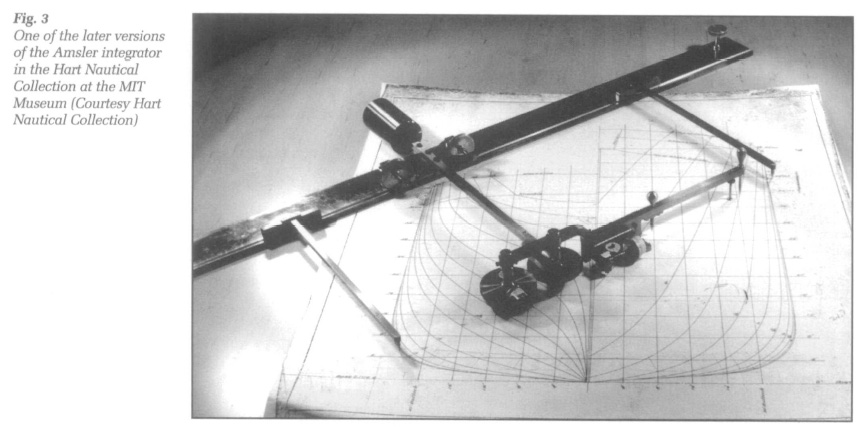
57 The integrator was an extension of the planimeter, which could be used to calculate the statical and inertial moments as well as the areas of closed and irregular curves (Fig. 3). It was conceived by Amsler in 1855 as another useful tool for engineers but not specifically for naval architects. The general market for the instrument was relatively small. Only 700 integrators were sold by his firm prior to Amsler's death in 1912, and the lack of a well-defined market may help to explain why it took Amsler until 1868 to produce an actual working model. Given that naval architects were already familiar with the planimeter and very rapidly saw the value of the integrator once they discovered its existence, it appears that there were a number of technical problems with the early version and that these problems took Amsler another decade to solve. It was not until 1878 that the first properly working integrator was imported to Britain. The first extended notice of the instrument in naval circles took place in 1880, when C. W. Merrifield presented a paper on the integrator to the Institution of Naval Architects.37
58 Extended discussion of the mathematical principles of the device will not be possible here, but those familiar with the mechanical calculators of an age just gone by will be aware that it is possible to arrange mechanical gearwheels to carry out mathematical functions. In the old calculators, the gears were used to carry out the arithmetic functions of adding, subtracting, multiplying and dividing. In the Amsler integrator, precisely calibrated gears and rollers were arranged to carry out the measuring and mathematical operations needed to find the areas, statical moments, and moments of inertia of irregular curves. The various cross and longitudinal sections found in ships' plans were just the sort of irregular shapes the integrator was able to deal with. Moreover, the data about areas and moments obtained was just the kind of information needed to calculate a ship's stability.
59 Arriving at the data for each section was a thing of incredible simplicity. The track for the instrument was laid down on the drawings and the instrument placed in the track. The pointer was placed on the drawing and readings were taken from the vernier scales attached to the cogwheels. The pointer was then used to trace the outiines of the irregular curve or section to be measured. The rollers turned the cogs, and new readings were taken from the scales. The initial readings were subtracted from the new readings. The results were then multiplied by a constant provided by the manufacturer. And that is all there was to it. In a few minutes the operator could know the area and moment of any section in the body, sheer, or half-breadth plans. The operation then had to repeated for the other sections. The resulting tables of areas and moments could then be combined by mathematical means to arrive at the location of the centre of buoyancy of the vessel in question.
60 What is striking is how the relevance of the instrument to reducing the burden of calculation in merchant steamers was immediately recognized. Thus, the very first person to speak after Merrifield's paper of 1880 was naval constructor William White and his immediate judgment was that: "any one who is familiar with ship calculations must know that this is a thing for which we have been longing for years because it will save us an immense amount ofmere routine work." For the price of a few pounds, he continued, the instrument could not only be used not to make calculations of displacement, the position of the metacentre, and the centre of buoyancy, but also calculations for the much more informative curves of displacement and stability. Indeed, White concluded, "there will be no excuse now if the curves of every merchant ship are not speedily calculated."38
61 The discussion following Merrifield's paper was limited. Most of the audience had never heard of the integrator before. Two years later, however, J. Harvard Biles presented another paper to the INA, showing how relevant it could be to the design of cargo steamers.39 This Biles accomplished by presenting curves of stability for several steamers built by his employers, the Clyde shipbuilding firm of Jas. and George Thompson. The paper was accompanied by a specimen calculation of stability that demonstrated the technique employed. Both the paper and the reaction to it focused directly on the reduction of the burden of calculation that the integrator made possible.
62 For instance, Biles reported that calculations made with the integrator were not only more simple, more accurate, and much shorter than those done by hand, but particularly stressed the fact that the work could be done by "comparatively unskilled labour." As proof he revealed that all the work of the curves he presented had been carried out by apprentices under sixteen years of age, whose only special qualifications were that they had been selected by competitive examination for entry to his drawing office. In addition, Biles told his audience, the specimen calculation appended to his paper was "completed by one apprentice in twelve working days, this being only the second that he had done. Others have been since done in less than one half that time. The cost of this calculation for labour did not exceed ten shillings."40 The members of his audience were duly impressed.41
63 The chief value of Biles's paper, however, was to show what the integrator could do with reference to the design problem facing naval architects, in the sense that rapid calculations now allowed the production of curves, and curves could reveal difficulties that were open to solution before a ship was built. One of the curves Biles presented, for example, was for the cargo steamer Thames. It showed that in the light condition this vessel actually had a negative righting force for the first 22 degrees of inclination. That is, if the ship was inclined for any reason, the couple formed by the centres of gravity and buoyancy would continue to turn the ship over. Not necessarily unsafe — the ship had been in operation for several years — these conditions did mean the ship had to be very carefully handled. In particular, as William Denny immediately pointed out, such a ship had to be so carefully loaded and unloaded that it spent much more time in port than other ships spent working.42 Furthermore, given her condition of stability, Denny argued the Thames could only take on the kind of deadweight cargoes that kept her loaded centre of gravity as low as possible. But deadweight cargo was the least profitable a ship could carry.43 These were just the kind of problems that could be identified in the design phase with the aid of stability curves that the integrator now made possible.
64 This being so, Denny went on to argue that using the integrator might help redress the kind of imbalance in the relationship between shipbuilders and shipowners seen in the case of the Daphne. As Denny put it, shipowners did not listen to shipbuilders when ordering vessels because they did not believe shipbuilders knew anything about making money in the carrying trade. That is why they ordered ships without bothering to consult the builder's opinion and why they were so thoroughly uninterested in hearing arcane talk about centres of gravity and curves of stability. The case of the Thames showed how the consideration of stability made possible by the integrator was directly related to operating profits. It was a clear case, Denny concluded, of scientific curves translated into money.44
The Outbreak
65 By 1882, shipbuilders had been alerted to the potential value of the integrator. Various naval architects working for different firms then set to work to perfect its uses. The result was what Sir Edward Reed referred to as a "notable outbreak of scientific development connected with the stability of ships" at the annual meeting of the Institution of Naval Architects in 1884.45 The session saw no less than eight papers on stability, almost all of them focusing on the surpassing usefulness of die Amsler integrator in reducing the burden of calculation in the design and operation of cargo steamers.
66 As before, a major theme was the surprise and in some cases astonishment at the remarkable speed and simplicity of the calculations made possible by the instrument. Most of the papers demonstrated ways of making the calculations even shorter. Unfortunately for our purposes, comparisons made with previous methods were often rather vague. No one gave a direct statement of how long it took to accomplish the same amount of work using the previously standard methods of Barnes. On the other hand, using an integrator in 1882, Biles's assistant had taken six days to complete the calculation of a curve for one displacement of a ship. A. Amsler, the son of the inventor (who had been hired by Denny), now presented a specimen calculation showing that he could find the displacement and vertical position of the centre of buoyancy of a ship in two hours; the longitudinal position of the metacentre in another two; and a complete calculation of the curve of stability for a single displacement in only eight hours.46 J. C. Spence announced that with his graphic methods he could find curves for all displacements in only three or four days.47
67 Of great interest to the members of the INA was the presentation by William Denny of two alternate methods of calculating what he believed to be brand new "cross curves" of stability, worked out independently by a Mr Fellows and a Mr Couwenberg of his own staff.48 Whereas in ordinary curves the righting arm was plotted against a changing angle of inclination for a single draught or displacement, the idea behind the cross curves was to take a single angle of inclination, plot the righting arm against changing displacement, then repeat the procedure for other angles of heel, thereby generating a wealth of information about the stability of the ship in various conditions. According to Denny, Fellows's method saved one-half the labour it would have taken to develop the same information by ordinary means. As Fellows' cross-curves involved the calculations of stability for six draughts, at six angles, and thus thirty-six curves of areas and moments, this was no mean achievement. Couwenberg reported that when he first came to Denny's yard it took about three days to determine the righting levers of one inclination for five draughts. He was now able to do the same work in nine hours. The plotting often waterlines took eleven hours. Integrating them to get cross-curves took only an hour and a half. From the cross curves, he reported, he could derive curves of the ordinary type for any displacement in an hour and a half.49
68 While shortening the calculations already contributed to economy in design, a second theme of the papers presented in 1884 was the way in which the integrator permitted further economies through the use of less skilled labour. Denny explained how the work of calculating curves was to be placed in the hands of the girls in his drawing office, freeing his more expensive staff for fresh lines of investigation.50 Biles judged the relative merits of the two alternate methods of making cross-curves, not on the grounds of accuracy, but on the grounds that Mr Couwenberg's method entailed the use of new tracings for multiple inclined waterlines, which had to be drawn by skilled draughts-men. In Mr Fellows' method, the integrator could be applied directly to the original body plan by unskilled labour, saving both time and money.51 In a similar vein, prominent naval architect MacFarlane Gray explained how he had worked out forms for the entry and calculation of readings from the integrator, "so that a boy can work them out without ever requiring to understand the calculation." Indeed, in his opinion, greater accuracy was obtained by apprentices using the integrator than those who actually had to think about what they were doing.52
69 In all the discussions of 1884 it was taken for granted that calculations made with the aid of the integrator were applicable to the design of cargo steamers, where the problem had been that an ordinary steamer was likely to carry almost any cargo and therefore likely to go to sea at almost any draft, its stability varying accordingly. Assessing the possibilities therefore required so many calculations that they simply were not done. With the integrator, a large number of curves could be developed. The information did not tell the designer where to place his centres of gravity and buoyancy. As before, this remained a matter of choice and compromise. With the new data, however, designers could at least avoid obviously unsafe or unprofitable failures. It was also still the case that the eventual behavior of the ship would really be governed by the cargo and not the ships themselves. On this point it was recognized that the masses of data found in curves and cross curves were directly applicable to what was referred to above as the operational problem. The difficulty was in what form the information should be given to those in charge of a vessel.
70 This difficulty was the subject of the paper by Francis Elgar, which served as the focus of discussion of the operational problem in 1884. As Elgar explained, the importance of stability in cargo ships had now been firmly established. The integrator allowed the multiple calculations of stability that were necessary. It was essential that the results be given to sea captains in order that they might operate their ships with safety. But he did not believe that that either ordinary curves or cross-curves would be of any practical value. In the first place:
71 In theory, this meant that sea captains would have to determine the conditions in which their ships were actually placed when loaded with different cargoes. But they simply did not have "the technical training and experience which is requisite of them to understand and deal with metacentres, centres of gravity, and curves of stability; and to make allowances or constant variations in draught of water, and position of centre of gravity which the different cargoes they carry render necessary." It was therefore "hopeless" to expect either shipowners or shipmasters to use metacentric heights and curves of stability as a practical guide in stowage. Instead, if it was ever to be used, stability information had to be put before them in a simpler form.54 Accordingly, he proposed that calculations made by builders should be reduced to practical instructions, indicating how high certain kinds of cargo should be stowed, in what place on what deck, what ballast should be carried with what loads and so on. This would appear to leave gaps in the continuum of different conditions to be accounted for. But Elgar was convinced that a captain's practical knowledge of his ship would take care of the difficulties and that "the proper use of stability calculations is not to supersede or interfere with that knowledge of a vessel's qualities which may be gained by experience, but to supplement and complete it in certain cases where it may be necessary."55
72 So many other speakers at the 1884 session referred to the applicability of the integrator to reducing the time necessary for stability calculations, to the economy of labour, and to both the design and operational problems of steamers that it would be tedious to repeat them all. It will, however, be worth noting the appreciative assessment of Sir Edward Reed. As he put it: "we happen to be living at a time when stability calculations have become a necessity on an enormous scale, and to supply them would have been at once difficult and expensive beyond limit if it had not been for the advent, so to speak, of this mechanical assistant."56
Conclusion
73 This paper began with the claim that an investigation of the significance of measured ships' plans in combination with the Amsler integrator could lead to an explanation for the widely perceived lack of science in nineteenth-century British shipbuilding. I have not attempted to argue that British naval architects were often more scientific than they get credit for, though a case could certainly be made. Rather I have tried to show that there were very real difficulties in the way of applying mathematical physical theory to problems of ship design at this time.
74 Crucial to my explanation of these problems is an understanding of the role of measured plans in shipbuilding, which were originally introduced as a means of reducing the costs of construction in contexts where economy was the overriding objective. These plans determined the shape of ships but did not solve problems concerning innovation in hull-forms, particularly the uncertain behavior that could result from the blending of conflicting qualities to meet the purpose. On the other hand, measured plans provided the foundation for the application of science in ship design, because they provided the kind of quantitative representation needed for predictive calculations. In this connection, we may note that the purpose of science in shipbuilding was not to serve as a source of innovation. Nor could theory be used to deduce the proper shape of ships. Its purpose was to check innovations in the shape of ships already arrived by other means and precisely embodied in detailed plans.
75 That the relationship between scientific theory and actual ships was mediated by the use of plans is an important point because without plans, use could not be made of predictive scientific theory. By the same token, theory had to be brought into a fruitful relationship with plans in order to have any real value. That is, it could be quite possible to build up a body of scientific theory. But if it could not be brought into an effective relationship with the plans, such a body of theory, for all its promise, was essentially useless in the design of individual vessels. Thus as scientifically minded naval architect Gabriel Harvey remarked in 1826: "The first mathematician in Europe may speculate forever on the forms of floating bodies; he may multiply his analytical combinations, and pile his highest order of integrals on each other; and yet, when called upon to make his practical applications, his formulae almost lose their identity, and all his golden speculations vanish."57
76 Stability provides a case in point. By 1800, an impressive body of theory had been established — indeed, after displacement, this was the only theory concerning floating bodies established on more or less correct principles. Moreover, means of applying the theory to ships' plans were available. And yet, between 1800 and 1860, government naval architects (who had good reasons to do so) rarely if ever calculated the stability of their designs. Between 1861 and 1870, they neither made ordinary calculations of stability in design nor made a habit of calculating the more useful curves of stability. Similarly, between 1870 and 1880, commercial builders failed to compute the stability of cargo steamers, despite the existence of sound theory, and despite the fact that they were now using plans to build ships.
77 These puzzling delays in the application of the science of stability are explained by the complex of interrelated problems I have referred to as the burden of calculation. In the first place, calculations were extremely long and complicated. Secondly, although the results might reveal potential difficulties, they gave very little guidance on how to change the plans to correct the difficulty. Changes still had to be made by eye, which called for feedback loops of re-drawing and re-calculating, but as long as the calculations took so long for so little guidance, there was simply little practical value in making them. Thirdly, calculations required a highly trained staff of mathematically trained professionals. This added greatly to the expense of design at a time when there was a great resistance to increasing the costs of shipbuilding through the employment of large design staffs. While all this was true of the navy, the burden for commercial builders was even greater, partly because of the greater numbers of calculations they had to make, but also because of conditions of trade in which designs were often given to them by shipowners. There was often no time for calculation and thus little financial reason to maintain a staff capable of making them.
78 The factors go a long way towards explaining the perceived lack of science in nineteenth-century British shipbuilding. But they also help to explain the reaction of shipbuilders to the Amsler integrator. It promised to shorten calculations to the point where the multiple curves of stability needed to address the design and operational problems of commercial ship design could be produced. Further, it permitted calculations to be made by relatively "inexpensive persons" and thus helped to overcome the economic burden of calculation in merchant practice.
79 Nevertheless, one must be cautious in claiming the integrator led to any "revolution" in the application of science to ship design. Edward Reed produced his Treatise on Stability in 1884, the first such treatise in the English language. In it he made large claims for the value of the instrument, particularly for its application to the design of merchant ships, his goal being to promote the professionalisation of commercial shipbuilding, and the instrument did become a standard piece of equipment in merchant ship design. Indeed the Hart Nautical Collection possesses a photo of the dozen or so integrators used by the students of MIT's school of naval architecture opened in 1893 — a proud display of raw computing power at the time. Nevertheless, there were problems in the way.
80 One of these was that as the cost of both warships and steamers increased, so did the need for more, and more accurate calculations. On this score, although some calculations were better than none, designers came to be concerned about the accuracy of results obtained with the assistance of the integrator.58 Secondly, those interested in promoting the naval science with the help of the integrator after 1884 — Reed, White, Elgar, Biles, Denny, Spence, and others — were almost all associated with the Institution of Naval Architects or trained at the navy's schools of naval architecture. In the navy, the battle for naval science had already been won, and more work needs to be done on the influence of the Institution of Naval Architects on British shipbuilding practice. But Pollard and Robertson have shown that only 23 of the 166 students who completed the course at the Royal School of Naval Architecture ended up working for private firms between 1864 and 1904.59 Thus it cannot be claimed that the advent of the integrator created a sudden demand for naval science in commercial shipbuilding.
81 Instead it would appear that the contextual conditions of the shipbuilding trade remained much the same. Builders continued to receive many of their designs from shipowners and were forced to contract for ships of known form in such a short period of time that extended calculations were impossible. This meant they could not afford to maintain professional staffs. The burden of calculation remained too high.60 Indeed, it might be claimed that the burden only really began to be lifted with the advent of the electronic computer in our own times.
The author would like to thank the Dibner Institute for the History of Science and Technology, the Social Sciences and Humanities Research Council of Canada, and Kurt Hasselbach of the Hart Nautical Collection for making this research possible.