Research Reports / Rapports de recherche
Reassembly of a Sixteenth-Century Basque Chalupa
1 The primary focus (1978-1985) by the Underwater Archaeological Services of Parks Canada in the seabed of Red Bay, Labrador, was a Basque galleon believed to be the San Juan, which sank in 1565. The ship had been engaged in sixteenth-century whaling operations in the Strait of Belle Isle. After careful excavation of the underwater site, the ship's timbers were dismantled, brought to the surface for thorough documentation, and replaced in a controlled reburial environment in the harbour.1 Also discovered in the harbour sediments were two other galleons and four smaller craft. This collection of boats — including a pinaza, a boat believed to be a batel and two chalupas — is the oldest of European construction to be recovered in North America. The remains of three of the four small craft were not reburied but were recovered and have undergone conservation treatment in Ottawa.
2 The chalupa was the Basque whaleboat. In Labrador, as in the Bay of Biscay, boats of this type operated from a shore station in order to hunt bowhead (Embalaena glacialis) and right (Balaena mystsetus) whales. Crews of six or seven men towed the carcasses back to the station for flensing and trying out. Chalupas were about eight metres in length and two metres in breadth, and were propelled primarily by oars, although a sailing rig was also carried. Boats used in North America were built in the Basque country, primarily of oak, and were shipped, either whole or in a disassembled state, on board the whaling ships along with all the other supplies necessary for conducting a season's whaling operations on the remote shore. The two chalupas recovered at Red Bay had five strakes per side plus stealers on grown frames. The top two strakes were lapped; the others laid flush. All the boats recovered from Red Bay have been studied and analysed by Brad Loewen, whose findings will be published as part of the final Red Bay excavation report.2
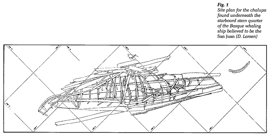
3 One of the chalupas recovered from Red Bay was buried under the stern quarter of the galleon and is particularly well-preserved (Fig. 1). About ninety per cent of the principal original structure is extant, including the stem, stern post, scarfed keel and mast step, in addition to most of the boat's nineteen frames and planks. A smaller proportion of the sheer wales, risers and other internal structures has survived. In late 1996 the decision was made to reassemble this boat.
4 The keel was laid for its second time 25 August 1997, and the last piece was installed 19 March 1998. The reassembly crew varied in size on any given day from one to five, but the principal participants, besides the author, were Rick Lane of Craig Johnson Restoration, Ottawa, who was primarily responsible for the metalwork, and Fred Werthman, boatbuilder, model maker and artist, of Marlinspike Heritage, Kingston.
 Display large image of Figure 1
5 In addition to having furthered our analysis of the artifact, the reassembled boat will become the primary display at Parks Canada's planned Visitor Orientation Centre in Red Bay. Red Bay is a National Historic Site, and World Heritage Site designation is a possibility. The boat was transported to Red Bay in June 1998.
Conservation
6 The wooden remains from three small boats recovered at Red Bay underwent a conservation treatment of impregnation with polyethylene glycol (PEG) and freeze-drying by staff of the Wet Organics Laboratory under the direction of Lorne Murdock at the Historic Resource Conservation Branch of Parks Canada. One hundred and fifty-three major pieces of timber and plank were used in the chalupa reassembly. Each piece was cleaned and its surface consolidated with polyvinyl acetate (PVA) before being handled by the reassembly crew.
7 A loading bay at the conservation facility on Walkley Road in Ottawa was temporarily converted into a shop dedicated to the chalupa's reassembly. Conservation staff, particularly Cliff Cook of the Wet Organics Laboratory, were readily at hand to provide materials-handling advice throughout the reassembly project. Having easy access to humidity chambers and other equipment and facilities, as well as tools and the expertise of personnel in other departments of the Conservation Branch, proved to be a great advantage.
 Display large image of Figure 2
8 Conservation staff were responsible for reattaching the smaller fragments of wood that were best secured with stainless steel pins and adhesives. Jade 403, Bulldog Grip (20 minute), or Acryloid B-72 in methanol were used, depending on what stage the adhesive was applied relative to the rehumidification of the wood. With the reassembly complete, an additional coat of PVA was applied to all the surfaces of the boat to provide further consolidation.
Supporting Framework and Transportation
9 For all the advantages of reassembling the boat in the Ottawa facilities, transportation of the completed boat over 2500 km to the place of final display posed a unique, and perhaps the project's most serious challenge: how to build a supporting frame that was portable, strong enough to adequately support the reassembled boat over sometimes rough roads, and yet still aesthetically pleasing for permanent display purposes.
10 We opted to anchor the boat to a specially constructed aluminum frame with a 4 x 4 x 3/16 inch (102 x 102 x 5-mm) section under the keel, flanked by two 2 x 3 x 1/8 inch (76 x 51 x 3-mm) lengths curved to shadow the hull outline in plan. Castor wheels and lifting rings were mounted temporarily for moving. The keel was secured directly to the base frame in four places. These points are not conspicuous in the final display; they are masked from the exterior by fairly flat floor sections, and by the floors themselves on the interior. On the base frame we erected five cradles per side. These cradles could only be fabricated after the boat was assembled to ensure a tight match to the boat's finished shape. Each cradle had a T section 3/8-inch (9-mm) thick aluminum; the surface bearing against the boat was l/2 inches (37 mm) wide. A single bolt secured each cradle on its inboard end providing a pivot point for the cradle to be positioned by struts equipped with threaded adjusters mounted on the outboard part of the base frame. All aluminum surfaces bearing the weight of the boat were insulated with 1/2 or 3/8-inch (12- or 9-mm) thick Evazote Foam.
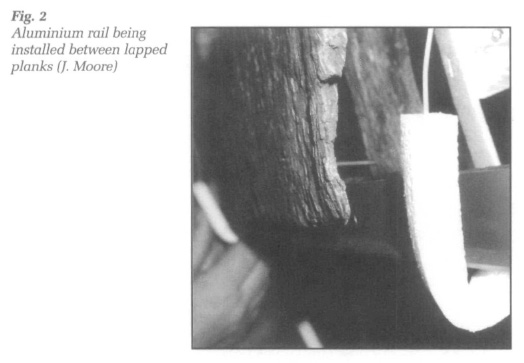
11 Three rails of L section aluminum, 3/32-inch (2.4 mm) thick and measuring 1 x 1/2 inch (25 x 12 mm), run the length of the boat on each side beneath the lapped planks and at the sheer wale level (Fig. 2). The concept for the rail installation is based on those used along the lapped seams of the Viking ships reassembled at Roskilde, Denmark. The rails impart considerable strength to the wooden hull and yet are light enough to be bent carefully by hand against the curvature dictated by the planks, although a shrink press was necessary to shape the rise. The 8-foot (2.4-m) lengths of rail were joined using aluminum solder. These rails were secured directly to the cradles. Additional floating cradles were installed to provide temporary additional support during transport. We counted on this combination of permanent and temporary cradle support, along with light anchoring, to provide the right mix of rigidity and flexibility to minimize the impact of vibration and jarring on the artifact during the move. An air-ride trailer with environmental controls was employed, and the frame was mounted on blocks of foam during transport to further dampen vibration.
Fastenings
12 In addition to the aluminum rails installed at the lap and sheer wale levels, we had planned to install rails of a T section along the flush-laid plank seams lower in the hull. In practice, our efforts to devise a satisfactory fabrication were not successful either from an aesthetic or a structural standpoint. We were able to abandon this plan thanks in large part to the considerable net strength imparted by fastenings we installed in the hull.
13 The original wrought iron fastenings had almost completely dissolved after four centuries submerged in salt water. We looked to the reuse of the fastening holes left in the boat's wooden components as a key to our reconstructing the original shape of the hull. We were uncertain, at first, as to how useful new fastenings would be in supporting the reassembled structure. Fastenings used for reassembly were fabricated of brass #6 threaded rod. To replicate the clenched end of a wrought iron nail, a piece of bent brass bar was braised on one end of the rod. The bent bar of each fastening was then individually fashioned by bending and grinding it to match the impression left in the wood from the clenched end of the original nail. The nut ends of these customized bolts were trimmed, ground smooth with a dremmel, and capped with a wax button sized to fit the nail head impression left in the wood and shaped to resemble a wrought iron nail head. The head and clench ends of the fastenings were finished in flat black. This way the new fastenings retained the basic appearance of the original fastenings and did not make new impressions in the surface of the wood.
14 Special fastenings include custom-made brass roves for fastenings between the lapped planks, and Spae-Naur's "Well Nuts" as dead-end anchors. The latter were used in fastening holes through which the point of the original nail had not exited. The fastening holes in this case had to be opened up to receive a neoprene sleeve containing a brass nut, which caused the sleeve to expand and lock when compressed. Some flexible wire fastenings and offset plates were used for holes that could not be made to line up perfectly. Less than ten per cent of our fastenings were out of alignment; taking into account that the wood shrank somewhat and that shrinkage rates vary with respect to the run of the grain, we were satisfied that the complex shape of the hull was reproduced with a high degree of accuracy.
15 We experienced a few fastening failures, but these failures pointed to areas under some stress needing additional bracing or reinforcement, and the failing of fastenings may have saved damage to the wooden structure. The number and distribution of brass fastenings, 521 installed throughout the hull, has imparted considerable strength to the reassembled boat.
Planks
16 The holding power of the fastenings was also dependent on the strength and integrity of the wood. The lap planks were the thinnest originally and also the planks to suffer the greatest deterioration. Those fastening holes found at the edge of these planks were often in very thin, weak wood. Generally, these planks could be held into the futtocks with larger washers on the fastenings as long as there was not too much strain. Unfortunately, the futtocks near their tops could also be badly deteriorated, or (in the case of 15 out of 38 futtocks above lower lap) missing altogether. Aluminum lap rails were critical in providing the longitudinal strength as well as stabilizing the hull structure at the level of the lap planks.
17 Generally, the starboard binder strake excepted, the wood of the lower planks provided excellent holding power for fastenings. The degree of preservation was so high that the great challenge was to rebend the flattened planks to their original assembled shape. Of course, it is not possible to steam PEG-treated planks. Scorching, the method probably used by the original builders, is even farther out of the question! Experimentation demonstrated that the oak became most flexible after a week in an environment of about ninety per cent relative humidity (RH) with a temperature of about thirty degrees Celsius. Any more heat caused the PEG to migrate.
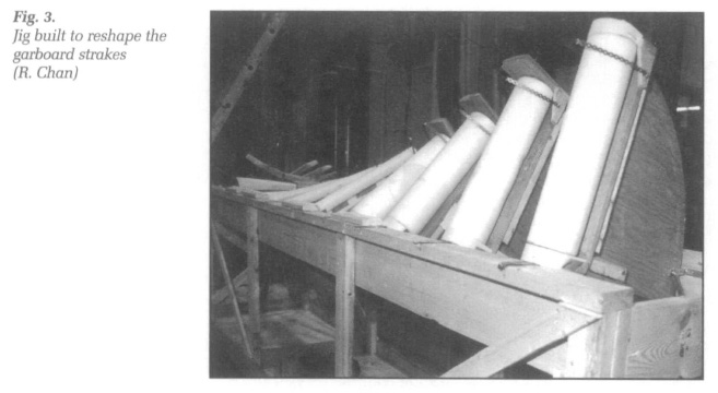
18 Strakes from different levels of the boat's structure provided distinct bending challenges. Two plank-bending jigs were constructed. The heaviest was required for the 1-inch (25-mm) thick garboards. These planks, when reassembled, needed to maintain a twist of nearly ninety degrees over half the boat's length; a slight over-bend had to be introduced prior to installing the planks. The jig consisted of a series of adjustable quadrants spaced approximately the same as the boat's frames. Those quadrants requiring the greatest movement were fitted with foam-covered rollers to minimize damage from friction to the surface of the planks (Fig. 3). Fitted with wheels, the whole apparatus could be moved in and out of the humidity chamber while increasing twist was introduced over the duration of about a week.
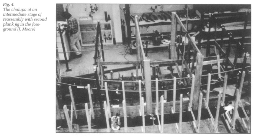
19 Planks above the garboard strake had to be not only twisted, but bent and spiled at the same time. Careful and detailed calculations were required for each plank before it was reshaped. A valuable aid in this process of calculation was the 1:5 scale model of the chalupa made by Fred Werthman, and a line drawing taken from it. Beside the boat, a second, simpler, plank jig was constructed into which planks from the strakes located above the level of the garboard and below the lap planks were placed (Fig. 4). The jig was built with frames stationed in parallel locations to the chalupa's frames from stem to stern. While shaping actually occurred in the workshop (45 to 55 per cent RH), it was preceded with a week's preparation in the humidity chamber for each plank. Usually, these planks were shaped to a slight over-bend in the first attempt, although on rare occasions a small hydraulic jack was employed to assist in the bending. Just as the PEG-treated planks proved resilient to judiciously placed jacks, they also suffered no noticeable negative effects from quick-drying, being brought directly from the humidity chamber for placement into the workshop jig.
 Display large image of Figure 4
20 Due to deterioration prior to recovery, however, many planks were split and broken. Often the support offered by fastenings, cradles or rails was insufficient to properly hold in place some of the loose or fragmented ends in the vicinity of breaks and splits. Over eighty assemblages of aluminum (tabs, straps and paired plates) were specially formed to provide the reinforcement necessary in each instance. These assemblages were naturally kept as small as possible. The paint chosen for all the metal work on the boat was a mossy grey-green, a colour that seemed to blend with the wood well, keeping the metalwork from being visually too intrusive.
Adjustable Moulds
21 The lap planks were thin enough that they could be bent directly onto the boat without prebending in a jig. But vital in providing stability for the direct bending of the lap planks and, indeed, to the whole structure during reassembly, was the use of internal moulds. Six moulds were constructed according to the shape dictated by the model reconstruction, and hung from overhead frames. Unlike analogous moulds used for new boat construction, however, our moulds were intended to be adjustable. Slotted gussets with bolts enabled us to combine all the advantages of a mould without impairing the boat's ability to "build itself back to its original form. The moulds were carefully mounted on the centreline and measurements to either side were used to monitor any anomalies in shape that emerged during reassembly. Hanging battens helped extend the moulds' monitoring range, as well as providing a handy support for setting the futtocks up in advance of the planking.
Timbers
22 The principal guides for any adjustment to the shape of the moulds were the floors and futtocks. While it was sometimes necessary to find an average deadrise, curvature or flair among these timbers at different stations, the floors and futtocks were fairly reliable in general and in little need of substantive rebending. More effort was required to straighten some of the boat's other timbers. The sheer wale fragments required some reshaping in a jig. The stem and stern post needed straightening in order to stand plum. Both sections of the scarfed keel also required straightening before construction could begin. The aft section of keel in particular had an exceptional number of knots and came out of conservation treatment badly twisted, deflected over eight inches off centre in one dimension.
23 Sometimes it was not possible to accurately anticipate, at the jig phase, the final shape of a timber. For example, the keel turns sharply up at each end before being scarfed to the stem and stern post. We had assumed that the keel ran straight to these turns. Indeed, this appears to have been the case at the stern, but attempts to secure the forward ends of the broad strake indicated that the forward end of the keel was actually rockered slightly, starting just over a metre aft of the keel-stem scarf. Rather than disassemble the work we had already completed, in order to put the forward keel section back in its jig, we constructed a hood of sheet plastic over the entire forward end of the boat into which both heat and humidity were introduced so that keel could be carefully stressed to its proper shape. This was one of four or five times we resorted to what we called our "humility" hood. It was placed over a portion of the partially reassembled boat in order to make corrections in shape made clearly necessary by the process of reassembly but not anticipated in the jig phase.
24 "Humility" is more than a term misappropriated to serve the reassembly crew's shop-floor wit. The attitude of humility is vital to the process of reassembly. In building a boat from scratch, the process for the builder is one of cutting, carving, bending and otherwise forcing the wood to conform to a preconception of what a boat should be. The reassembly process is very much the reverse of this. The boat's remains are all that survive to express the builder's will. Only by recognizing, respecting and responding to all that the eroded chalupa timbers have to tell us can we come close to reaching something of a communion with that Basque boatbuilder whose life was lived 400 years ago. The process is not one that simply ends with a beautiful public display, but one that can deeply enhance our perception of the ancient manual and oral traditions that informed the builder's craft, and provided him with the mental template through which his considerable skills found their expression in a boat tailored to meet the requirements of the whalemen who used it. Only through our humility can the boat rebuild itself and thereby tell its story.
Postscript
25 The "reconstruction" of a boat or a ship from archeological remains is a lengthy and involved process.3 It begins even as the archeological data are being carefully collected from the site. The process of an abstract reconstruction evolves as the provenience of structural elements is established and as an understanding of wrecking and other site formation processes emerges. Through detailed documentation of each structural fragment, its shape, tool marks, wear marks and fastenings, a function and interrelatedness among the fragments can be posited. Initial reconstruction analysis expands and refines these field interpretations graphically by a variety of two-dimensional means. Interpretation of most archeologically recorded vessels only reaches this abstract phase of reconstruction. For some sites, complexity and a high level of recorded detail make building a three-dimensional research model a possibility, or even a necessity for adequate analysis. For both the Basque whaling ship believed to be the San Juan and the chalupa, detailed archeological models were made, allowing for a much more thorough analysis and a better understanding than would have otherwise been possible. Relatively few vessels are given this level of attention. But only a handful in the world have been actually reassembled, providing the ultimate level of reconstruction analysis. The reassembled chalupa is better and more accurately reconstructed than it could be in model form, no matter how carefully made. In addition to furthering archeological analysis, the completed boat will be a most memorable tool for public interpretation and commemoration of Basque activity in the Red Bay area (Fig. 5).
26 Building a replica may be part of the three-dimensional stage in reconstructing archeological material. With the depth of analysis achieved through the well-preserved remains of the chalupa, an accurate replica can be confidently produced. The flow of information would not be one way, however; a replica building project would still further our research by helping to firm up some construction details and by allowing for experimentation with sailing rig and rowing arrangements. It is hoped that one or more replicas of the sixteenth-century Basque chalupa can be built in Red Bay, Labrador, before the official opening of the National Historic Site there in 1999.
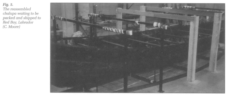 Display large image of Figure 5
The author would like to acknowledge some of those who contributed most to the process of reassembling the chalupa. In addition to Fred Werthman and Rick Lane, the reassembly crew included Jonathan Moore, Lisa McCarthy and co-op student Matthew Bruce. Special thanks are due to Willis Stevens and Robert Grenier of Underwater Archaeological Services, and Arlene King of the Newfoundland New Initiatives Unit, Parks Canada, who, by demonstrating confidence and providing support, enabled us to see the process through. In addition to Cliff Cook, we the team owe thanks to Andrea Recht and Dee Stubbs at the Wet Organics Lab of the Historic Resource Conservation Branch. Thanks as well go to Rock Chan and George Vandervlugt for their assistance with photographic documentation. Final dianks go to the archeological field crew in Red Bay who began the chalupa reconstruction process, but particularly Marcel Gingras, Charles Bradley and Brad Loewen, who had done most of the analysis before we laid the keel for the second time.