Vol. 16 No. 2 January 2005
Modeling and Validating the Grabbing Forces of Hydraulic Log Grapples Used in Forest Operations
Jingxin Wang
West Virginia University
Morgantown, WV, USA
Chris B. LeDoux
USDA Forest Servic
Morgantown, WV, USA
Lihai Wang
Northeast Forestry University
Harbin, China
ABSTRACT
The grabbing forces of log grapples were modeled
and analyzed mathematically under operating conditions
when grabbing logs from compact log piles and from
bunch-like log piles. The grabbing forces are closely related to
the structural parameters of the grapple, the weight of
the grapple, and the weight of the log grabbed. An
operational model grapple was designed and tested to
validate grabbing forces of the mathematical models while
grabbing logs from five alternative diameter classes under
two different working conditions. The working conditions
and log sizes affected the grabbing forces significantly.
Validation results suggest that the mathematical models
developed can be used to estimate the grabbing forces
required in the design process of log grapples. The
results can be used by equipment manufacturers and
researchers involved in the engineering design of grapples used
in harvesting operations.
Keywords: Grabbing forces, log grapples, logging,
forest operations, equipment manufacturing.
INTRODUCTION
Log grapples are mechanisms for handling timber,
which can be attached to crane systems, knuckle-boom
loaders, grapple skidders, forwarders, or other machines for
loading, unloading, sorting, and stacking operations either
in log yards or on logging sites. A grapple can be
classified as either a radial or an axial grapple depending on its holding
position of the logs. Radial grapples are widely
used and can be further classified into electrically driven
or hydraulically driven based on the power source used.
The hydraulically driven grapples are the most popular
models and can be grouped into inclined cylinder, vertical
cylinder, and horizontal cylinder grapples based on the
cylinder's position [11].
The theoretical aspects of grapples that must be
considered during the design process are the forces that
act on the grapple, structural properties, parameters and
kinematics of the grapple [10]. Since 1950, several
methods have been applied to analyzing and computing the
grabbing resistance or grabbing forces of log grapples.
The design concepts and the grabbing resistance of log
grapples were first introduced and described by Taybep [6].
The tension force of electric hoists was described for
grapples using the energy method [4]. The energy
method calculates the grabbing resistance from the energy
consumption point of view, that is, the work done by
the external force should be equal to the energy consumed
by moving the logs or the displacement work of the log
grapple according to the laws of energy conservation [6, 10].
The displacement of a log grapple component,
however, is very difficult to measure in the grabbing process
using the energy method. Therefore, it is hard to use this
method to determine the grabbing resistance accurately. The
grabbing resistance of grapples was also calculated based
on the friction forces among the logs [7]. This
approach considered only the log movements regardless of the
structure of the grapple. The direction and acted point of
grabbing resistance could not be determined by this approach.
The patterns of log movement also varied greatly
with working conditions. The grabbing resistance force
could be calculated based on the lever equilibrium principle [3].
The advantage of this method is that the value and
direction of the force could be determined graphically.
This method, however, might result in a certain error and
would be impossible to use if there are more than two
unknown variables in the model. The forces acting on the tongs
of a log grapple could be assumed with a certain
distribution, which was then used to determine the grabbing
forces []. The main problem with this approach is how to
determine the distribution pattern. A literature review of
log grapples described the basic conditions and
development of log grapples in forest operations [9, 11].
Many applications of the use of log grapples can
be found in Scandinavian and North American forest
operations, especially grapples used as attachments to skidders.
The use of grapple skidders in conjunction with
shovel logging has been shown to reduce soil disturbance
and road building costs [1]. Kleunder and Stokes [2]
reported that grapple skidders had consistently higher
volumes and lower times per cycle when compared to cable skidders.
Grapple skidders have been used extensively in the
Southern U.S. for many years to form a harvesting system
configuration that along with feller-bunchers has shown
to have utilization rates of up to 75 percent [8].
However, only a few references could be obtained about the
design or mechanics of log grapples. Since the grabbing force
is the key factor that is used to determine the structure
and parameters of a grapple during the design process, it
is essential to develop better models in order to
understand the grabbing forces involved. Accordingly, in this
research we (1) developed a new mathematical model
for estimating grapple resistance forces, (2) validated it
by comparing the mathematical results with actual
operational measurements, and (3) used the mathematical model
to illustrate the relationships between the grabbing force
and the working conditions and log size.
MODELLING GRABBING FORCES
Knuckle-boom loaders and forwarders use their
self-contained log grapples to load logs onto tractor-trailers
or unload logs from trucks onto the deck while
grapple skidders usually grabbed tree bunches and extracted
them from the woods to the landing. The ways that the logs
are grabbed can be categorized into the following
working conditions:
- Grabbing logs from a compact pile;
- Grabbing logs as a bundle.
The grabbing force is the force exerted on the tong
and is used to close the tongs of the grapple. Grabbing
resistance is the reaction force of the grabbing force. In
order to model the grabbing force, the grabbing resistance
must be identified first. Three assumptions were made
about the grabbing resistance forces acting on the tongs of
the grapple while grabbing:
- The grapple holds the total weight of the
grabbed logs when the tongs are closed and the tips of
tongs are juxtaposed to each other;
- Three frictions occurred while grabbing - friction
among logs, friction between logs and the inside face of
the tong, and the friction between logs and the
outside face of the tong. The resultants of frictions that
make up the grabbing resistance are considered in the
process of modeling;
- While grabbing, the grabbing resistance force
acting on the tong follows a fixed distribution pattern.
Two fixed distribution patterns were used for modeling
the grabbing resistance (Figure 1b and 1c), especially for
determining the acting point of the resistance on
the tong [10]. One pattern,
 , is one for grabbing logs from a compact log pile (Figure 1b),
while
, is one for grabbing logs from a compact log pile (Figure 1b),
while  is the pattern for modeling grabbing
a bundle of logs (Figure 1c). Where p(x)
represents distribution pattern of the grabbing resistance
force along the tong; x is the vertical distance from the
tip to the joint of the tong; and k is the coefficient
associated with the structure and weight of the grapple.
is the pattern for modeling grabbing
a bundle of logs (Figure 1c). Where p(x)
represents distribution pattern of the grabbing resistance
force along the tong; x is the vertical distance from the
tip to the joint of the tong; and k is the coefficient
associated with the structure and weight of the grapple.
Model For Grabbing Compact Log Piles
When the grapple starts to grab the logs, the
tongs' tips are first placed in the gap between logs. Then
the grapple's tongs are gradually closed. Since the grapple
is symmetric in structure, the forces acted on the log
grapple can be described as shown in Figure 1a. The
resistance distribution on the external face of the tong is discrete
and usually does not follow a pattern and varies
depending on the method of grabbing. Therefore, the resultant
force is used to represent this resistance in the model.
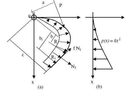
Figure 1. Diagram of the forces acting on the tong of the grapple.
If we let R be the resultant force of
ΣRi, then the moment around point
o for the grapple at its equilibrium state
can be expressed as:
 (1)
(1)
where, P = the grabbing force (Newtons);
Ri =
ith component of the grabbing resistance;
a, c, bi = the positions of forces related to
the structure of the grapple;
f = the friction coefficient between the logs
and the tong of the grapple;
N1 = the normal pressure of the grapple
exerted on the outside the tongs;
If the resultant force R is substituted for
ΣRi in equation (1), a coefficient
k1 must be used for adjusting the
difference between the assumed resultant resistance and
the actual resistance and k1 takes a value between 1.0 and
1.3 [12]. To simplify the modeling process, it is not
necessary to leave mo(N1) in equation (1) since it will enhance
the grabbing force. Hence,
 (2)
(2)
If we let mo(R) (the moment of forces around point
o) represent R´b (b is the vertical distance of R to point
o), equation (2) can be expressed as,
 (3)
(3)
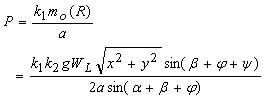
Therefore, the grabbing force
P acting on the tong of the grapple is expressed as:
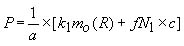 (4)
(4)
where, a, c,
f are known and mo(R) and
N1 need to be determined.
Calculating mo(R)
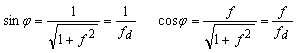
In Figure 2,
X1OY1 is a fixed coordinate and the
coordinate of XOY moves with the tong's movement. If we
let WG be the weight of the grapple in Kg,
WL be the weight of the grabbed logs in Kg, R be the resultant force
of grabbing resistance in Newtons (N),
Hf, Vf be the internal forces in the tong's joint (N),
a be the angle between axes X and
X1, and b be the angle between axis X and
the tangent line of acting point of R; then the moment
around joint o can be expressed as:
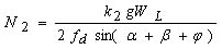
mo (R) =
mo (F) + mo (N2 )
(5)
The
mo(N2) and
mo(F) are then expressed as,
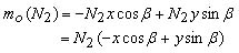 (6)
(6)
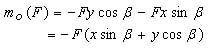 (7)
(7)
If we substitute
mo(F) and
mo(N2) in equation (5)
into equations (6) and (7), we have,
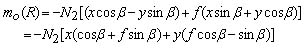 (8)
(8)
Then in order to determine
N2, F and N2 need to be reflected and resolved on the axes
X1 and Y1. Then, we can solve for
Rx1 and Ry1 as follows:
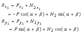 (9)
(9)
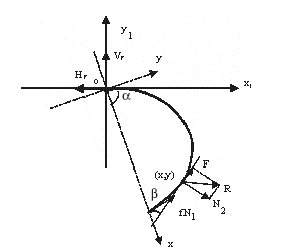
Figure 2. Model diagram of the grabbing resistance.
The grapple is assumed to hold the total weight
of grabbed logs when the grapple's tongs are closed and
the tips of tongs are juxtaposed. Under such a working
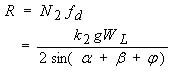
condition, Ry1 acting on a tong of the grapple can be
expressed as:
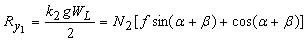 (10)
(10)
where, k2 = coefficient of the unbalanced load in the
grapple (k2 = 1.0 to 1.2) [10];
g = acceleration of gravity (9.8
m/s2);
Therefore,
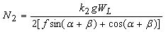 (11)
(11)
Then if we let
 (12)
(12)
Substituting
N2 in equation (8) into equation (12),
we have,
 (13)
(13)
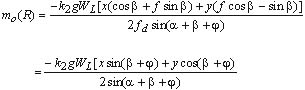
Calculating the Value, Acting Direction and Point of R
From equation (9), we can express R as follows:
 (14)
(14)
Therefore,
 (15)
(15)
If we let q represent the acting direction of R and
q be the angle between R and axis X1, then we can solve
the tgq as follows:
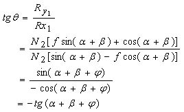 (16)
(16)
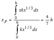
The acting point of R on the tong can be
determined based on the distribution of grabbing resistances
along the tong. If we let xp denote the vertical distance from the acting point to the joint of the grapple and
h be the distance between the joint and tip of the grapple (Figure
3), we have,
For  (the grabbing of a log pile), we can solve for xp as follows:
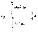 (17)
(17)
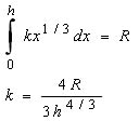
Then k can be calculated as follows:
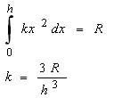 (18)
(18)
For  (the grabbing of a log bundle),
 (19)
(19)
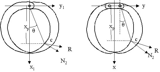
Figure 3. Diagrams of the acting points and directions of the grabbing resistances.
Similarly, k can be calculated by the following
expression,
 (20)
(20)
Once we solve for
xp, the acting point of R can be
determined, which is point C (Figure 3). Then,
g becomes the angle between
N2 and R, which computed as follows:
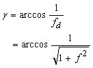 (21)
(21)
Calculating N1
When the grapple completes the grabbing and the
tongs are closed, the following equation is always true.
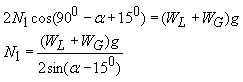 (22)
(22)
Where, the angle of
150 is the angle between the line segment along the tong's tip section and the
horizontal line. Substituting equations (13) and (22) into
equation (4), we have,
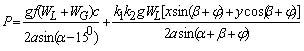 (23)
(23)
Then if we let 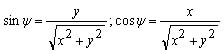 ; equation (23) can be simplified as:
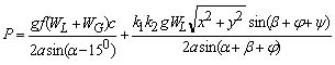 (24)
(24)
Since angles of a + b +
y and a + b + j could be greater than 180°, the absolute values of
sin(a + b + y) and sin(a + b + j) must be used in equations (24)
and (25).
Model For Grabbing A Log Bundle
If the grapple grabs the log bundle,
fN1c = 0 in equation (4). Therefore,
 (25)
(25)
In a practical application,
a and b are known and a is between 0 and
900 and can be expressed as:
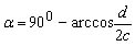 (26)
(26)
where, d = the distance between two tips of the
grapple's tongs (d is between 0 and the tongs
maximum spread);
c = the distance between the tip of tong and
the joint of grapple.
Then if the curve function of the grapple's tong is
known, say y = f(x), then b can be obtained as follows:
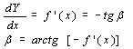 (27)
(27)
MODEL VALIDATION TESTS
An operational log grapple was designed and tested
in the Mechanical Lab at the Northeast Forestry
University, Harbin, China (Figure 4). Two inclined hydraulic
cylinders were used for opening and closing the tongs of
the grapple and two 3-ton pulling/pressing sensors were
attached to the end of each cylinder for recording the
grabbing forces. An additional cylinder was also adopted
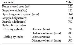
for lifting the grapple. The technical parameters of the
grapple are listed in Table 1. The pulling/pressing
sensors were calibrated on the material testing machine and
the linear relationship between the load and fluctuation
height was obtained by using the least square method.
Table 1. Parameters of the grapple used in the
tests.
l = kbh (28)
where l = load in N;
h = height of the calibration curve under a
specific load;
kb = coefficient of calibration;
kb can be computed based on the following equation.
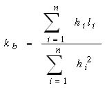 (29)
(29)
where,
hi = ith height of the calibration curve under load
li;
li =
ith load;
n = the number of times loads were summed
during calibration;
kb = constants 204.2 N/mm and 367.5 N/mm
respectively for the sensors we calibrated.
The logs grabbed during the tests were grouped into
4, 8, 12, 16, and 20 cm scaling diameters and were 2 m
in length. The species used included Siberian spruce,
birch, and other pines. A total sample of 15 logs was tested
for each diameter class. Since logs were labeled at the
ends, their positions in the log piles were the same before
each test. Two working conditions were also simulated for
each diameter class.
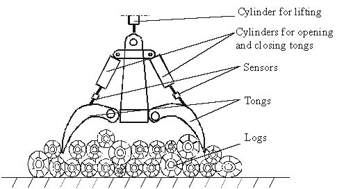
Figure 4. Diagram of the structure of the grapple tested.
Three variables were measured for each experiment
- grabbing force 1, grabbing force 2, and the grabbed log
weight. The two sensors attached between the
grabbing cylinders and the tongs of the log grapple measured
the grabbing force 1 and 2 respectively. A total of 150
experiments were conducted to measure the weight of
the grabbed logs and the grabbing forces. An analysis
of variance (ANOVA) model was used to determine if
differences existed in the weight of the grabbed logs and
the grabbing forces. The ANOVA model can be stated
as follows:
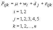 (30)
(30)
Where
Fijk represents the
kth observation of the grabbing force or the grabbed log weight under the
ith working condition and the
jth log diameter treatment,
m is the mean of each response variable,
wi is the effect of
ith working condition,
dj is the effect of
jth log diameter,
eijk is an error component that represents all uncontrolled variability,
and n is the number of observations within each
treatment. The grabbed log weights averaged 164.7 and 180.9 Kg
for grabbing the compact piles and the log bundles
respectively and differed significantly (F = 109.88; df = 1, 149;
P = 0.0001) (Table 2).
There is a significant difference among the grabbed
log weights across diameter classes (F = 427.47; df = 4, 149;
P = 0.0001) and ranged from 131.1 Kg for 4 cm logs to
215.0 Kg for 20 cm logs. The grabbing force 1 was
significantly different between working conditions (F = 116.28; df = 1,
149; P = 0.0001). On average 9545.2 N was needed to
close the tongs and grab the logs on compact piles and
7872.0.3 N to grab the log bundles. The grabbing force 1
was between 6997.1 N and 10420.3 N for grabbing logs of 4
to 20 cm in scaling diameter and was significantly
different among diameter classes (F = 63.94; df = 4, 149; P = 0.0001).
Similarly, there is also a significant difference of the
grabbing force 2 between working conditions (F = 38.85; df =
1, 149; P = 0.0001) with an average of 8293.0 N for
grabbing compact piles and 7320.9 N for grabbing the log bundles.
Grabbing force 2 varied from 6262.8 N when grabbing
4-cm logs to 9006.6 N when grabbing 20-cm logs.
Grabbing force 2 was not significantly different between 8 and
12 cm, 16 and 20 cm diameter classes. If grabbing force 1
and grabbing force 2 were averaged, the average
grabbing force was also significantly different between
working conditions with 8919.1 N for the grabbing of compact
log piles and 7596.4 N for the grabbing of log bundles (F
= 88.80; df = 1, 149; P = 0.0001). The average grabbing
force was between 6630.0 N and 9713.4 N when grabbing
logs of 4 to 20 cm. There was no significant difference
when grabbing logs between 16 and 20 cm in scaling diameter.
The unit grabbing force was also measured by the ratio
of the average grabbing force and the grabbed log weight.
There was a significant difference between grabbing
compact log piles and log bundles with the average of
55.3 and 42.0 N/Kg respectively (F = 191.01; df = 1,149; P
= 0.0001). However, the unit grabbing force did not
differed significantly among diameter classes of 4, 8, and 12 as
well as between logs of 16- and 20-cm in diameter.
Table 2. Means and significance levels of statistics for the log grapple during tests1.
| | Work conditions | Diameter (cm) |
|
| | Compact | Bundle | 4 | 8 | 12 | 16 | 20 |
| Grabbed log weight (Kg) | 164.7a | 180.9b | 131.1c | 152.7d | 160.2e | 205.1f | 215.0g |
| Grabbing force 1 (N) | 9545.2a | 7872.0b | 6997.1c | 7852.3d | 8529.0e | 9744.2f | 10420.3g |
| Grabbing force 2 (N) | 8293.0a | 7320.9a | 6262.8c | 7317.7d | 7631.7d | 8816.1e | 9006.6e |
| Average grabbing force2 (N) | 8919.1a | 7596.4b | 6630.0c | 7585.0d | 8080.4e | 9280.1f | 9713.4f |
| Unit grabbing force (N/Kg)3 | 55.3a | 42.0b | 50.9c | 49.9c | 51.3c | 45.4d | 45.7d |
1Means with the same letter in a row are not significantly different at the 5 percent level with Duncan's Multiple-Range Test.
2The average of grabbing force 1 and grabbing force 2.
3The ratio of average grabbing force and grabbed log weight.
The models for the grabbing forces were validated
by comparing the calculated mean grabbing forces
achieved by the mathematical models with the means of the measured
grabbing forces under the two different working
conditions (Table 3). The grabbing forces were calculated
by equation (24) for grabbing compact log piles and by
equation (25) for grabbing log bundles. When the tongs of
the operational grapple being tested were closed and the
tong's tips were juxtaposed, the parameters used in
equations (24) and (25) were assigned as follows:
α = 14.860 +
900 = 104.860 = 1.83 radian
ß = 390 =
0.68 radian
x = 42 cm
y = 13 cm
a = 13 cm
c = 48 cm
k1 = 1.1
k2 =1.15
f = 0.5
The mean of the grabbed log weights under each
combination of working condition and diameter class was
also used for input to compute the grabbing force. The
average grabbing forces of operational variables for
grabbing force 1 and grabbing force 2 was comparable.
The difference between calculated and measured
grabbing forces never exceeded 11 percent for grabbing
compact log piles and never exceeded 10 percent for
grabbing log bundles (Table 3). Generally speaking, the
differences of the grabbing forces for grabbing compact log piles
was higher than those for grabbing log bundles. For
example, the difference in grabbing logs of 16cm in a compact
pile was over 10.2 percent while it was only 5.3 percent
for grabbing log bundles. This is because the grabbing of
a compact log pile was a more complicated situation
compared to grabbing log bundles and the grabbing force
was affected not only by the logs being grabbed but also from
the forces of the logs underneath the log grapple.
Based on the validation test comparisons we concluded that
the models could be used to estimate the grabbing forces
of the grapple.
DISCUSSION AND CONCLUSIONS
The grabbing forces of hydraulic grapples are
closely related to the grabbing capacity, the weight, the
structural parameters of the grapple, and the grabbed
log/bundle weight. The mathematical models developed can be
used to estimate not only the grabbing forces, but also
the magnitude, acting direction and grabbing resistance
on the tong of the grapple under working conditions of
grabbing a compact log pile or a log bundle.
Validation tests indicated that the grabbing
resistance or grabbing force was significantly affected by log size
in terms of diameter class and working condition.
Grabbing log bundles is easier than grabbing logs from
compact piles. The grabbing forces needed for grabbing
compact log piles were about 15% more than the force needed
for grabbing log bundles. The grabbing resistance
increased as the log size increased. Correspondingly, the
average grabbing force increased about 46% from 6630.0 N
when grabbing 4-cm logs to 9713.4 N when grabbing 20-cm logs.
However, if the logs are extremely large, the grapple
may only be able to handle a single log per grab. Under
such situations, the grabbing force needed is only to hold
the one log. The unit grabbing forces generally
decreased with the log size and decreased about 10% from 50.9
to 45.7 N/Kg.
Table 3. Comparisons of the grabbing forces between calculated and measured forces.
| Working conditions | Scaling diameter (cm) | Grabbed log weight (Kg) | Calculated grabbing force (N) | Measured average grabbing force (N) | Difference (%) |
|
| | 4 | 125.9 | 7237.1 | 7460.5 | -3.1 |
| | 8 | 146.7 | 8253.4 | 8434.2 | -2.2 |
| Compact | 12 | 149.7 | 8400.0 | 9115.0 | -3.4 |
| | 16 | 198.5 | 10784.4 | 9685.5 | +10.2 |
| | 20 | 202.8 | 10994.5 | 9900.6 | +9.9 |
| |
| | 4 | 136.3 | 5438.7 | 5799.5 | -6.6 |
| | 8 | 158.8 | 6270.8 | 6735.9 | -7.4 |
| Bundle | 12 | 170.8 | 6800.3 | 7045.7 | -3.6 |
| | 16 | 211.7 | 8428.8 | 8874.7 | -5.3 |
| | 20 | 227.1 | 9041.9 | 9526.5 | -5.4 |
Since the grabbed log weight is the only parameter
in the mathematical models that comes from the logs being
grabbed, the models developed could not directly
identify the relationship between the grabbing resistance/force
and log diameter or other characteristics. The difference
between calculated grabbing forces and the measured
average grabbing forces for grabbing compact log piles
was higher compared to grabbing log bundles. This
suggests that other factors such as inertia resistance due to
the logs' movement should be considered in future models.
However, the difference for grabbing log bundles was
between -7.4 and -3.6 percent and the calculated
grabbing forces were consistently lower than the measured forces.
This is because the friction resistance between the
outside face of tongs and the ground and/or other
objects might exist and needs to be considered. Therefore, a
coefficient of 1.1 needs to be added to the models to adjust
the grabbing forces so that the model predictions line up
with the experimental observations. Log movements and
the friction resistance between logs should be explored
during grabbing in the future studies. Further tests might
be needed to examine how the structure of the log
grapple and the logs from larger diameter classes affect the
grabbing forces.
The validation test comparisons showed small
differences between the mathematical and the operational
results. Based on these results we concluded that the
mathematical models can be used to estimate grabbing
forces for grabbing logs from compact piles and from log
bundles typically encountered in most logging operations.
A spreadsheet program is available to users upon
request from the authors that simplifies the calculations.
AUTHOR CONTACT
Prof. Jingxin Wang can be reached by email at --
jxwang@wvu.edu
REFERENCES
[1] Egan, A. F. 1999. Residual stand damage after
shovel logging and conventional ground skidding in an
Appalachian hardwood stand. Forest Products
Journal. 49(6): 88-92.
[2] Kleunder, R. A. and B. J. Stokes. 1994.
Productivity and costs of three harvesting methods.
Southern J. of Applied Forestry. 18(4): 168-174.
[3] Li, K. and Y. Zhu. 1979. Calculation of the
grabbing force of the log grapple under certain working
condition. Forestry Research and Design. No. 2. [In
Chinese].
[4] Shen, X. 1983. How to determine the power of
the electrical hoist used on log grapple. Forest
Logging Science, No. 2. [In Chinese].
[5] Shi, J. 1981. Design of log grapple for
unloading trees-length. J. of Northeast Forestry
University. 9(3):45-54. [In Chinese].
[6] Taybep, B. A. 1957. Kinematics of the
grabbing mechanism. Forest Machinery Institute of
Moscow, Publication No. 7, Moscow, Russia.
[7] Taybep, B. A. 1960. The grabbing mechanism.
Forest Machinery Institute of Moscow. Moscow, Russia.
[8] Thompson, J. D. 2001. Calculating utilization
rates for rubber-tired grapple skidders in the
Southern United States. Proceedings of the
24th Annual COFE Meeting. Snowshoe, West Virginia. July 18-19,
2001: pp. 29-31.
[9] Wang, J. 1989. Basic conditions and
developments of log grapple used both in China and abroad.
Forest Logging Science. No. 4: 39-48. [In Chinese].
[10] Wang, J. 1990. Study on the theories of log
grapples. Ph.D. Dissertation. Northeast Forestry
University, Harbin, China. 311 pp.
[11] Wang, J. and G. Li. 1993. A review of log
grapple used in China. J. of Forest
Engineering. 4(2): 33-36.
[12] Wang, Z. and Z. Fan. 1985. Design and calculation
of the log grapple. Forestry Machinery. No. 3:
23-30. [In Chinese].
The authors are, respectively, Assistant Professor,
Division of Forestry, West Virginia University, Project
Leader, Northeastern Research Station, USDA Forest
Service, and Professor, College of Engineering and
Technology, Northeast Forestry University.