Vol.9 No.1 January 1998
Y.Y. Gerasimov and V.S. Siounev
Petrozavodsk State University
Petrozavodsk, Russia
The authors are Professor and Associate Professor, respectively, at the Forest Engineering Faculty.
ABSTRACT
The optimal model for a hydraulic crane compound scheme is discussed for four types of mobile logging machines: secondary transport truck or lorry, skidder (feller-skidder), forwarder, and harvester (feller-buncher).
Keywords: Design, logging, optimization, harvester, forwarder, truck, crane, forest engineering.
INTRODUCTION
The established practice of using cranes on mobile forest machines indicates that it is more reasonable to locate a crane on the cab or with the cab on a rotating platform. This compound scheme improves the field of vision, the user comfort, and reduces the crane weight. However, the crane-holding cabs of forest machines (e.g., VALMET 824, FMG 200 BGN, FMG 678 MINI) need additional strengthening of the cab or frame (Figure 1). The location of the crane with the cab on a rotating platform makes the forest machine structure heavier and more complicated (Figure 2). This type of crane compound scheme is used mostly on the powerful feller-bunchers (e.g., Russian ML-20, LP-19A) and harvesters (e.g., VALMET 901).
Figure 1. Pillar on a cab.
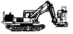
Figure 2. Pillar with a cab on rotating platform.
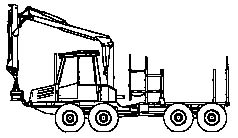
Figure 3. Pillar behind a cab on the front frame.
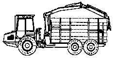
Figure 4. Pillar behind a cab on the back frame.
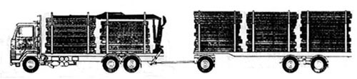
Figure 5. Pillar with hydraulic outriggers behind a machine on the console part of a frame.
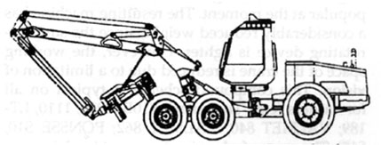
Figure 6. Pillar in the front of a cab on the front frame.
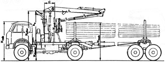
Figure 7. Main geometric parameters of the crane.
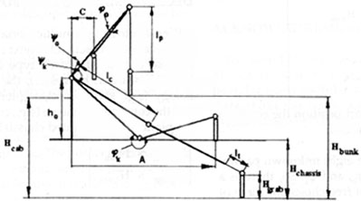
Figure 8. Skeleton compound scheme.
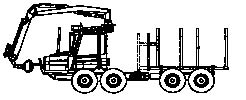
The location of the crane on a pillar behind the cab, and this crane-cab combination on the front (Figure 3) or back (Figure 4) of the frame is the most popular at the moment. The resulting machine has a considerably reduced weight, since the support-rotating device is lighter. However, the working space of the crane is reduced due to a limitation of vision. This compound scheme is typical on all forwarders (e.g., Timberjack 810B, 1010, 1110, LT-189; VALMET 840, VALMET 862; PONSSE S10, S15). The crane of a logging transport truck is more often located on special pillars with hydraulic outriggers behind the machine on the console part of the frame (Figure 5). This compound scheme is made to serve the bunk decks of both the base machine and the trailer.
In the final compound scheme (Figure 6) the crane located in the front the cab of the harvester is especially popular (e.g., FMG 990, FMG 0470, FMG 0410, FMG 0450, VALMET 701). This scheme provides a fine view of the working space.
DESIGN VARIABLES SELECTION
The hydraulic crane of a forest machine as an object of design is characterized by the following main parameters (Figure 7):
In addition, the crane compound scheme on a forest machine is determined by the base machine parameters and the dimensions of the bunk device:
Depending on the type of forest machine and attachments (e.g., harvester, feller-buncher, feller-skidder) it is necessary to take into consideration:
The general characteristics of the harvested trees (e.g., average diameter - D, tree's species - S) should be taken into account also.
The problem of the synthesis of the design parameters for the crane can be divided into two dependent optimization tasks:
The optimization of the skeleton compound scheme may be formulated by a vector diagram of the initial data {L, M, Mrot, Q, Hchassis, Hcab, Hmax, Hgrab, A, B, C, Cfell, D, and S}, thus finding:
CRITERIA SELECTION
Generally, this problem has an unlimited number of solutions. Therefore, the problem of substantiation of the main design parameters for the crane skeleton can be formulated as an optimization, which predetermines the choice of the optimization criteria:
![]() (1)
(1)
where
FUNCTIONAL CONSTRAINTS
Truck crane
The specifications of a logging transport truck crane in general are characterized by four main boundary positions (Figure 8), which limit the independent variables of the system (1). The first position is determined by the transport location of the crane on an empty truck, the second by the log or the sortments location on the ground, the third by the nearness of the bunk deck relative to the pillar rotation axis, and the fourth by the greatest crane working height during the loading-unloading of cargo. Others positions of the crane are intermediates (including the transport position of the crane on a fully loaded crane on a fully loaded truck) which do not have an influence on the synthesis of the skeleton scheme.
It is sufficient to consider loading conditions for solving the crane skeleton compound problem. In this case the calculation problem of the crane parameters relates to the four points problem above.
Loading conditions include:
Using crane compound schemes (Figures 1, 3, 4, and 5), the height of a cart load of timber is limited by the maximum overall machine dimensions (Hmax):
Hbunk < Hmax . (3)
pFor other schemes this limitation is not relevant.
Thus when constructing the crane "skeleton" compound scheme it is sufficient to consider four main points: determined by the crane position and location in transport, the location of the logs on the ground, and the two crane positions, which are determined by the bank or the receiving device location.
The following specification limits for a logging truck crane are:
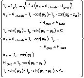 (4)
(4)
For fully loaded transport position the equation lc+ lp+ Hgrap < A may be added.
The five equations have eight unknown parameters: lc, lp, lt, ho, y0, yk, j0, and jk. So, there is a fundamental possibility of free choice for three of them. These choices may have an optimizational character.
 (5)
(5)
The same specification limits may be found for other types of cranes.
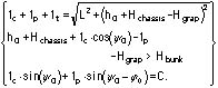
Skidder with clamping bunk or feller-skidder crane
For the crane of a feller-skidder or skidder the equation system will be:
Forwarder crane
For the forwarder crane the equations will be:
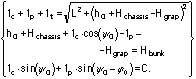 (6)
(6)
Harvester or feller-buncher
For a harvester or feller-buncher (e.g., Russian ML-20, LP-19A) the following may be applied:
![]() (7)
(7)
DECISION MAKING PROCEDURE
We call into being a multicriteria, multiparametric optimization problem.
Our next step is to make an optimal decision for each type of machine (e.g.,
truck, forwarder, harvester), the harvesting technology (e.g., short-wood,
log-length, whole-tree) and the compound scheme (e.g., crane on cab, rotating
platform, or mounted chassis).
![]() (8)
(8)
In mathematical form the optimization task for truck (short-wood technology, crane on chassis; Figure 8) is the result of the combination of system (1) and formula (4). Moreover, the design variables lc, lp, lt, ho should be positive.
A minimum crane weight (Wweight) will be achieved by aspiring for a minimum pillar length (hoÆmin). This limit is formalized by installing conditions of contact on the mobile crane elements with outward contours of the chassis, platform, and bunk:
There Hpillar = h0 + Hchassis.
The working space criterion Wspace follows:
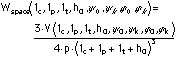 (9)
(9)
where
V = volume of working space.
From the maximization point of the working space criterion Wspace it is expedient to make y0 = 0 and ho --> min.
The length of the telescopic section is chosen from the specified dimensions of the hydraulic cylinders, and also takes into account the special features of the telescopic lengthener type. There is an outboom length (lp) limit:/
lp > Lmin + lmin, (10)
where
Solution of the equations (4) and inequality systems (3), (8), and (10) make it possible to design a hydraulic crane "skeleton" compound scheme for a logging truck.
The same procedures may be applied to other types of crane equipment. The number of constraints equations in these models are less than the main design parameters. So, the decision-making procedure must have a non-linear programming algorithm[3].
CONCLUSIONS
In this paper a systematic method for the design of forest machinery cranes is described on the basis of crane weight and working space criteria. The method allows for the synthesis of the crane "skeleton" according to machinery type, crane location on a machine, and logging technology.
For the case study the results showed the necessity of separate designs of forest cranes by machinery type: truck, skidder or feller-skidder, forwarder, and harvester or feller-buncher. This statement is trivial but important, because some machinery construction firms have tried to use the same crane for the different types of machines.
The case study also showed that the functional constraints play the key role in the final decision making, especially, for a truck or lorry.
The present procedure of the "skeleton" compound scheme synthesis supports forest engineers by providing them with the knowledge for designing the new optimal machinery or choosing the appropriate manufacturing machines.
The speed of movement of machine elements (their combination - speed of load) is a key factor in productivity. The set (combination) of measures of the skeleton influences productivity although power transmission has the greatest influence. Therefore, the future study should be devoted to the compound scheme synthesis of the lever transmission mechanisms of the cranes. Moreover, it is an interesting task to take into account additional criteria such as, for example, the position precision of a harvester head
or a grapple and the output of the machinery.ACKNOWLEDGEMENT
We would like to thank Prof. Pertti Harstela and Mr. Lauri Sikanen from Joensuu University, Finland, for many useful discussions and suggestions throughout this work, and Mark Richman for the English language edition.
REFERENCES
[1] Gerasimov, Yu. Yu. and V.S. Siounev. 1997. Harvester crane key parameters
optimization in European Russian Pines. Journal of Forest Engineering 8(1):6374.
[Return to text]
[2] Lee, T.W. and D.C.H. Yang. 1983. On the evaluation of manipulator
workspace. Trans. ASME J. Mechanism, Transm. Autom. Design. 105(5): 7077.
[Return to text]
[3] Reklaitis, G.V., A. Ravindran, and K.M. Ragsdell. 1983. Engineering
optimization: Methods and applications. John Wiley and Sons, Inc., New
York. 349 pp.
[Return to text]