
Display large image of Figure 1
January, 2000, vol.11 no.1
Yu. Yu. Gerasimov and V.S. Siounev
Petrozavodsk State University
Petrozavodsk, Russia
ABSTRACT
Previously we published some results of the procedure for the improvement of intermediate technology and machinery performance criteria. The aim of the present paper is to describe the model of the middle level of hierarchy - the optimization of the hydraulic cylinder operating mechanisms. Drive and transmission mechanisms for forest machinery crane synthesis are discussed as optimizations for boom operating mechanisms and outboom operating mechanisms. Concentration is on the static part of this problem. Although the speed of movement of the crane elements affects productivity, it is not taken into account in this study. Future studies will take into consideration a dynamic analysis and output of machinery.
The results of this study show the necessity to separate the design of different types of forest machine cranes. For example, for the parallel crane type, a modification of the proposed algorithms is necessary.
This paper may be useful for forest machine designers as well as university students, who take courses in forest machine design..
Keywords: design, optimization, operating mechanism, forest crane, boom, outboom.
The authors are, respectively, Professor and Associate Professor, Forest Engineering Faculty.
INTRODUCTION
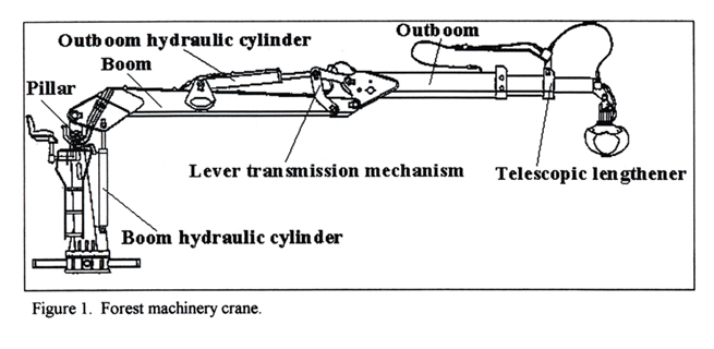
Drive and transmission mechanisms for forest machinery cranes involve a system of hydraulic cylinders and mechanical levers (Figure1). The hydraulic cylinders create working forces for turning the boom and outboom. Lever mechanisms transmit the forces to crane elements.
In an ideal case from the static point of view, the forest crane hydraulic transmission mechanisms would ensure equality of the loading moment (LM) and the driving moment (DM) at every point in the working space.
In a real case, complete equality of the LM and the DM for all of a crane�s positions can not be achieved due to construction limitations and the limits of the hydraulic cylinder�s standard range. Therefore, the problem of crane mechanism synthesis is formulated as an optimization: to select transmission mechanism parameters, at which the maximum ratio of the DM to the LM is minimized, as well as more than one or equal one for the whole scope of changes for the angles:
min (max[{DM(R, n)LM(R, n)}>1])
(s,d,r) Ψ0 < Ψ <Ψk,
φ0 < φ < φk
(1)
where
DM (Ψ,φ) = the driving moment function;
LM (Ψ,φ) = the loading moment function;
s = the hydraulic cylinder stroke;
d = the hydraulic cylinder diameter;
r = the hydraulic cylinder mounting coordi-
nates and the sizes of lever mechanism
elements;
Ψ0 - Ψk = the range of the boom turn angles;
φ0 - φk = the range of the outboom turn angles.
In addition to consideration of construction and materials on the operating parameters, it is necessary to set the corresponding area and functional limitations. This is done with a multiparameteral nonlinear programming optimization problem.
Display large image of Figure 1
Figure 1. Forest machinery crane.
BOOM OPERATING MECHANISM
A scheme for a boom operating mechanism is presented in Figure 2.
The input data for the calculations are the key design parameters for the crane frame or �skeleton� part as we called it in our previous studies [2, 3]:
• the lengths of the crane boom (lc),
• the length of the crane outboom (lp),
• the length of the telescopic lengthener (lt),
• the length of the pillar (ho),
• the limiting angles for boom rotation (Ψ0 and Ψk),
• the limiting angles for outboom rotation (φ0 and φk ).
There is also a standardized range for the hydraulic cylinders characterized by the combination of: cylinder diameter (d), stroke (s), and length (l) of the cylinders when completely retracted.

Display large image of Figure 2
Figure 2. Scheme of the boom operating mechanism.
According to condition (1), it is required to select hydraulic cylinders and their mounting coordinates so that they ensure that the angular rotation of the boom within the set range of angles during the power stroke meet working requirements. There are no special limitations on the mounting coordinates for the hydraulic cylinder except that cylinder should be located close to the crane sections.
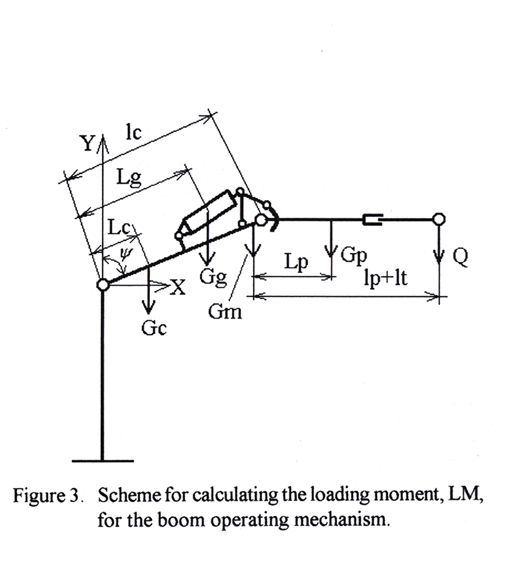
For calculation of the boom loading moment LM, the moment forces for the crane sections and the load weights were determined for the column-boom junction hinge (Figure 3). Note that the greatest moment (if horizontal components are not in consideration) will correspond to when the boom is in the horizontal position with the outboom at maximum extension:
For Ψ0 < Ψ < π/2:
LM(Ψ) = {Gc • Lc+Gg • Lg + (Gm + Gp + Q) • lc} x
x sin(Ψ)+Gp • Lp +Q (lp+lt);
(2)
For π/2 < Ψ < Ψk , outboom in line with boom:
LM(Ψ) = {Gc • Lc+Gg • Lg+(Gm+Gp+Q) • lc +
+Gp • Lp +Q • (lp+lt)} • sin(Q),
(3)

Display large image of Figure 3
Figure 3. Scheme for calculating the loading moment, LM, for the boom operation mechanism.
where
Q = the force of gravity acting on the load and the working device;
Gc, Gp, Gg, and Gm = the forces of gravity acting on the boom, the outboom with extension, the outboom hydraulic cylinder, and the lever mechanism, respectively;
Lc, Lg, and Lp = the distances between the sections, junction hinges and centers of gravity for: the boom; the outboom hydraulic cylinder; and the outboom, respectively.
The DM is determined in the following way:
Mg (Ψ) = Fg • pg • h (Q) • ng, (4)
where
Fg = the area of the boom hydraulic cylinder piston;
pg = the pressure on the hydraulic system;
ng = efficiency (ng ≈ 0.95);
h(Ψ) = the arm of the force on the boom hydraulic cylinder.
The arm, h(Ψ), in the immovable coordinates system with its center at point O (Figure 2) is determined by the formula:
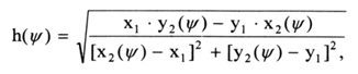
where
x1 = r1;
y1 = - r2;
x2(Ψ) = r3 • sin(Ψ) + r4 • cos(Ψ);
y2(Ψ) = r3 • cos•(Ψ) - r4 • sin(Ψ).
The boom hydraulic cylinder mounting axis coordinates meet the following conditions:
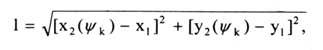
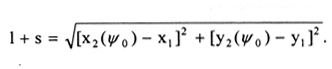
where
l = the length of the hydraulic cylinder when the stroke fully retracted;
s = the hydraulic cylinder stroke.
The optimum solution is as follows:
min (max[Fg • pg • ng • h (Ψ)/ML(Ψ)>1])
(s,d,r) Ψ0 < Ψ < Ψk,
(8)
where
r = {r1, r2, r3, r4} is the hydraulic cylinder mounting coordinates
(see Figure 2) accounting for the conditions (6) and (7).
Two independent equations (6) and (7)
correspond to four operating parameters for the multiple r. A solution
can be found with an optimization method, for example, the random search
method [4].
From an engineering point of view it is worth while to simplify
the problem into a particular form. In such a form the search for a solution
may be presented in the following algorithm:
1. Set the pressure for the hydraulic system pg, and the sizes for standard hydraulic cylinders (diameters d and strokes s).
2. Set the construction limits r1 and r4: to ensure the hydraulic cylinder is mounted a safe distance from the construction surfaces and the kinematics axis.
3. Then set the boundary constraints for r2 and r3.
4. Solve equations (6) and (7) for each hydraulic cylinder within its standard range. Get the corresponding optimum values of r2 and r3.
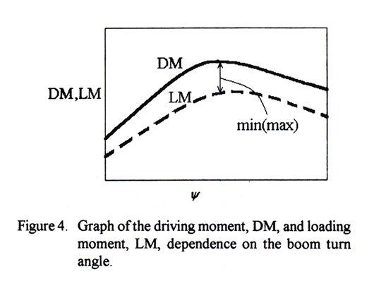
5. Change the angle Ψ with in the range from Ψ0 to Ψk (for example, by 5° increments). Graph the DM and LM dependence on the boom turn angle for each hydraulic cylinder (Figure 4) using formulas (2) through (5). Choose the maximum value for the ratio of DM over LM.
6. Choose the hydraulic cylinder, characterized by the minimum value for the maximum ratio of DM over LM. Fix that hydraulic cylinder and its mounting coordinates.
7. If necessary, set new values for pg, d, and s, then return to step 1.

Display large image of Figure 4
Figure 4. Graph of the driving moment, DM, and the loading moment, LM, dependence on the boom turn angle.
This algorithm can be easily solved using a personal computer with any mathematical software, for example, MathCAD.
OUTBOOM OPERATING MECHANISM
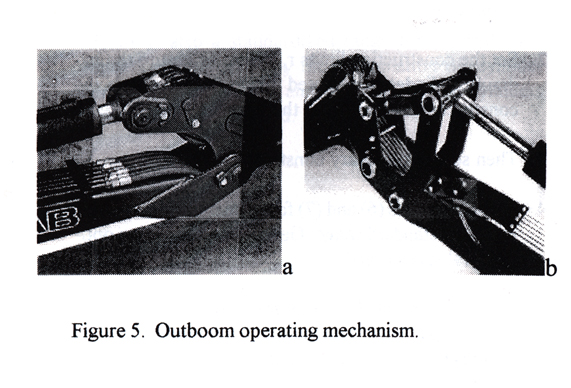
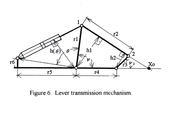
The most commonly used outboom operating mechanism schemes as shown in Figure 5. The scheme shown in Figure 5a is used in the most powerful models of forest cranes. The algorithm for arranging the operating mechanism for this scheme is almost the same as for the boom operating mechanism previously described. The hydraulic lever mechanism shown in Figure 5b is more popular in modern forest cranes. For further detail of this second mechanism, the lever transmission mechanism is shown in Figure 6.

Display large image of Figure 5
Figure 5. Outboom operating mechanism

Display large image of Figure 6
Figure 6. Lever transmission mechanism.
Optimization calculations for this mechanism require the same input data as for the previous mechanism.
It is necessary to select a hydraulic cylinders, its mounting coordinates, and the sizes of the lever mechanism r1, r2, r3, r4, r5, r6 (Figure 6) so that the angle shifts of the boom within the set range of angles on the power stroke are complete and according to formula (1). There are no additional restrictions to the mounting coordinates, other than that the hydraulic cylinder is located close to the crane surface.
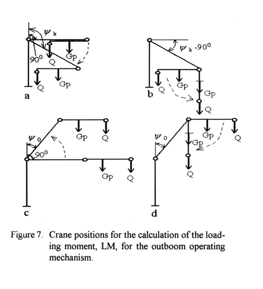
Determination of the LAM for the outcome operating mechanism is more complicated than for the boom operating mechanism. The LAM is connected by both the boom turn angle, Ψ, and the outcome turn angle, φ. To illustrate this, the four crane positions are shown in Figure 7.

Display large image of Figure 7
Figure 7. Crane positions for the calculation of the loading mechanism, LM, for the outboom operating mechanism.
Figures 7a and 7b show the stages of
movement when the hydraulic level mechanism develops maximum negative moments
(the hydraulic cylinder head stop is reached).
In Figure 7a, the boom turn angle changes from π/2 to Ψk
while the outcome maintains the same horizontal orientation, i.e. the LM
is a constant and can be determined as follows:
Ml(Ψ, φ) = Q • lp + Gg • Lp
π/2 < Ψ < Ψk
(9)
φ = Ψ - π/2
In Figure 7b, the value of Ψ = Ψk and the outboom moves from the horizontal to the vertical, i.e. the LM changes according to the sine law from its maximum value to zero:
LM(Ψ, φ) = Q • lp + Gg • Lp) • sin(φ - Ψk )
φk = π/2 < φk ,
(10)
Ψ = Ψk = const.
Figures 7c and 7d show the stages of movement when the hydraulic lever mechanism develops maximum positive moments (the hydraulic cylinder rod stop is reached).
In Figure 7c, the boom turn angle changes from π/2 to Ψ0 , the outboom maintains the same horizontal orientation, i.e. the LM is a constant and can be determined as follows:
LM(Ψ, φ) = Q • lp + Gg • Lp ,
(11)
Ψ0 < Ψ < π/2
In Figure 7d, the value of Ψ = Ψ0 and the outboom moves from the horizontal to the vertical, i.e. the LM changes from its maximum value to zero according to the sine law:
LM(Ψ, φ) = Q • lp + Gp • Lp) • sin(φ - Ψk )
Ψ0 < φ < Ψ0 + π/2
(12)
Ψ = Ψ0 = const.
The maximum moment of the outboom operating mechanism (MM) is determined as follows:
MM(Ψ, φ) = MC( Ψ, φ) • i(r) (13)
where
MC(Ψ, φ ) = the moment developed by the hydraulic cylinder;
i(r) = the hydraulic lever mechanism transmission function.
The transmission function, i(r), is
expressed with the hydraulic lever mechanism parameters (Figure 6):
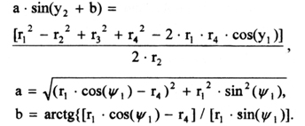
i(r) = h2/h1 = (x0 - r4) / x0. (14)
To determine x0, draw a line through points 1 and 2 (Figure 6), then assume their coordinates can be determined by the equation of a line on a plane:
(y - y1) / (y2 - y1) = (x - x1) / (x2 - x1). (15)
The intersection of that line and the axis X gives the point x0, therefore from equation (15) get:
x0 = x1 - y1 (x2 - x1) / (y2 - y1). (16)
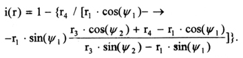
Because
x1 = r1 • cos(Ψ1); x2 = r3 • cos(Ψ2) + r4,
y1 = r1 • sin(Ψ1 ); y2 = r3 • sin(Ψ2 ),
(17)
expression (14) transforms into the following:
To determine the relationship between the angles Ψ1 and Ψ2 use the following condition:
(x1 - x2)2 + (y1 - y2)2 = (r2)2 , (19)
which after some transformations result in the following:
Finally, the desired relationship is reached:
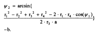
(20)
The moment of the hydraulic cylinder is determined in the following way:
MC(Ψ, π) = Fg • pg • h(θ) • ng , (21)
where
Fg = the area of the piston for the outboom hydraulic
cylinder;
pg = the pressure on the hydraulic system;
ng = the efficiency (ng » 0.95);
h(θ) = the arm of the force on the outboom hydraulic cyl-
inder.
The arm, h(θ), in an immovable coordinates system with its center at point O (Figure 6) determined by the formula:
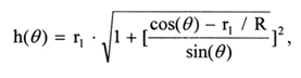
(22)
where
θ = the angle dependent on the hydraulic cylinder stroke.
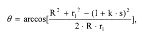
where
l = the hydraulic cylinder length when the piston rod is
completely withdrawn;
s = the maximum stroke for the outboom hydraulic cylinder;
k = a coefficient, showing the degree that the piston
rod is extended (0<k<1).
There is a functional relationship between angles Ψ1 and θ :
Ψ1 = π/2 - θ - arccos(r5 / R).
(24)
It is necessary to set the following functional
restrictions on the multitude r :
r1 • sin(Ψ1 ) > r6,
r1 + r3 > r4.
Finally, the optimum solution for the operating parameters is written in the following form:
min (max[{i(r) • MC(Ψ,φ)/LM(Ψ,φ)}>1])
(s,d,r) Ψ0 < Ψ < Ψk,
(25)
φ0 < φ < φk,
where
r = { r1, r2, r3, r4, r5, r6} is the multitude of the joining
sizes accounting for the restriction:
r1 • sin(Ψ1 ) > r6.
Once again, the number of independent equations is fewer than
the number of design variables. The solution can therefore be found using
an optimization method, for example, the random search method.
The optimization algorithm is:
This algorithm can be easily utilized with a personal computer using any code language or mathematical software, for example, MathCAD.

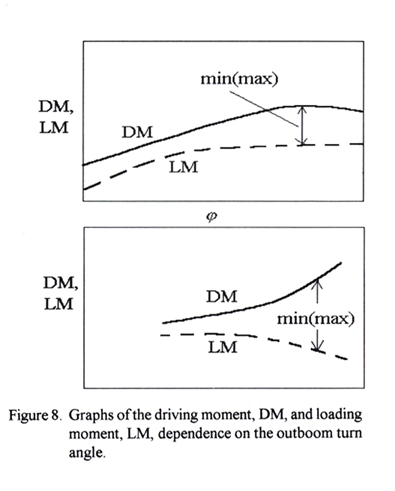
Display large image of Figure 8
Figure 8. Graphs of the driving moment, DM, and the loading moment, LM, dependence on the outboom turn angle.
CONCLUSIONS
The method and algorithms proposed above support forest engineers in providing them with the knowledge to design new optimal crane constructions. It allows to work out optimum drive and transmission mechanisms for forest machinery cranes.
This method also allows designers to synthesize the hydraulic boom operating and outboom operating mechanisms for traditional types of forest cranes located on machines. The algorithms can be easily utilized with a personal computers.
ACKNOWLEDGMENTS
We would like to thank Prof. Pertti Harstela, Mr. Lauri Sikanen from Joensuu University, Mr. Pasi Poikonen from Indufor Ltd. Helsinki, Finland, for many useful discussions and suggestions throughout this work and Mark Richman for English language edition.
REFERENCES
[1] Y.Y. Gerasimov and V.K. Khlustov. 1996 Thinning Regime Optimization
in European Russian Pines. J. of For.Eng.7(2):7-16.
[Return to text]
[2] Y.Y. Gerasimov and V.S. Siounev. 1997 Harvester crane key parameters:
optimization in European Russian pines. J. of For.Eng.8(1):63-73.
[Return to text]
[3] Y.Y. Gerasimov and V.S. Siounev. 1998. Forest Machinery Crane Compound
Scheme Synthesis: �skeleton� part Harvester crane key parameters: optimization
in European Russian pines. J. of For.Eng.9(1):10 p.
[Return to text]
[4] Reklaitis G.V., Ravindran A. and Ragsdell K.M. 1983. Engineering
Optimiza tion: Methods and Applications. John Wiley and Sons, Inc. New
York. 349 pp.
[Return to text]