
Display large image of Figure 1
Vol. 11 No. 2 July 2000
Halvor Torgersen
Norwegian Forest Research Institute (NISK)
Ås, Norway
ABSTRACT
This paper describes an investigation of fatigue resistance in different steel wire rope constructions used in Norwegian cable logging operations. Test results indicate the following:
Keywords: Cable logging, compacted steel wire rope, block, fatigue, angle of deflection.
The author is a PhD student at the Norwegian Forest Research Institute.
INTRODUCTION
Mobile yarders, lighter equipment and better methods have made it possible to decrease rigging time for cable logging systems. One task in a rigging operation is carrying blocks into the logging field. Workers prefer to carry smaller, lighter blocks, usually smaller than the recommended size for the wire rope used. The repeated bending of the individual wires, as the rope passes over the sheave, causes fatigue. Sheave diameter should be of an adequate size relative to the rope used in order to prevent excessive fatigue in the rope.
Two compacted steel wire ropes for cable logging have been introduced in Norway. Compacted wire ropes were introduced mainly because of their longer life expectancy; a mechanical treatment to increase the metallic cross-sectional area results in a higher strength-to-diameter ratio. (This may, for example, include a swaging process wherein the rope or its strands are drawn through a die.) Compacted steel wire ropes tend, however, to have greater bending stiffness, and decreased fatigue resistance may be a problem where compacted ropes are used on small sheaves.
Compacted ropes are divided into three main categories on the basis of compaction method: (1) the whole rope is compacted, (2) the individual strands are compacted, and (3) the strands and the whole rope are compacted.
OBJECTIVES
Our knowledge concerning fatigue and the effect of varying angles of deflection on compacted steel wire ropes is limited. Such knowledge is of great importance to cable logging contractors when they choose their equipment and organise their work.
The goal of this study is to establish life expectancies for and measure wear on two compacted ropes and one standard rope used on sheaves with varying angles of deflection. The new knowledge about rope performance under bending stress will give cable logging contractors more precise criteria for selecting the right ropes, blocks, and rigging procedures.
MATERIALS AND METHODS
Wire ropes
Three ropes of a 6x19 construction with right regular lay and an independent wire rope core were tested:
Blocks
The blocks used in the test were four open-sheave [5], 8-inch Nalco with a groove diameter of 180 mm. This block was selected because it is delivered with the Norwegian Owren T3 and T400 Cable yarders and is in common use among cable logger entrepreneurs in Norway.
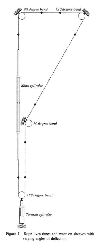
The sheave is much harder than other commonly used sheaves in Norwegian forestry. Sheave hardness was measured to 618 HV30 using the Vickers method (equal to 588 HB) on unused sheaves at NISK. The two ball bearings in the blocks had a static load limit equal to 2x15 kN. The sheaves were positioned to give the rope 30°, 90°, 120°, and 180° angles of deflection, respectively (see Figure 1). There were no signs of wear in the sheave surfaces after the test was finished.
Table 1.Rope specifications.
| Rope | Manufacturer | Diameter | Construction | Minimum breaking load |
Weight | Tensile strength |
| A | Wuxi city steel rope plant | 12.0 mm | 6X25 IWRC RHRL Warrington seale. Largest wire: 0.8mm* |
93.0 kN | 0.60 kg/m | 1770 N/mm2 |
| B | Wirerope industries Ltd | 12.7 mm | 6X25 IWRC RHRL Compacted filler. Largest wire: 1.0mm* |
166 kN | 0.94 kg/m | 1770 N/mm2 |
| C | Canadian manufacturer | 12.7 mm | 6X25 IWRC RHRL Compacted filler. Largest wire: 1.05mm* |
171 kN* | 0.96 kg/m* | 1770 N/mm2 |
| * Values measured at NISK. | ||||||
Investigating equipment for wire ropes can generally be classified in three groups:
This study falls in category 2.
The three wire rope types were tested in a test rig consisting of four blocks, a cylinder to adjust rope tension, and a cylinder to move the rope back and forth. Each piston stroke subjected the rope to an acceleration period, a constant velocity period, and a retardation period. Piston stroke length in the main cylinder was 3.2 m. Test ropes were 19 m long, had a mean velocity of 1.5 m/sec, and a tension force of 40 kN.
Each test rope was moved in cycles back and forth until failure at one of the bends. The test method was designed to simulate, as closely as possible, the actual conditions for ropes and blocks in use in Norwegian cable logging:
Three replications of each compacted rope construction were conducted; four replications were conducted of the reference rope.
Broken surface wires
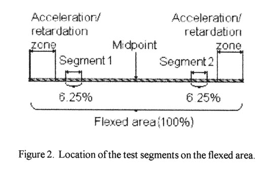
The number of broken wires on the outside of a wire rope provides an index of its general condition and indicates whether or not it must be considered for replacement [10]. When a rope failed at one of the bends, its remaining flexed parts were failure tested to measure remaining breaking strength. Visible broken wires were identified at intervals of 500 cycles on the surface of two 200-mm long test segments. These were located 875 mm to 1075 mm from the midpoint of each flexed area of the rope. They were placed there to give easy access for inspection and to avoid the acceleration and retardation zones.
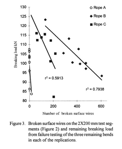
Total area tested was 12.5% of the length of each flexed area (Figure 2). The objective of this part of the test was to estimate the remaining breaking load (Figure 3) from the number of wire failures on the test segments.
Figure 1: Rope lives times and wear on sheaves with varying angles of deflection.
Display large image of Figure 1
Figure 2: Location of the test segments on the flexed area.
Display large image of Figure 2
RESULTS
The ropes were cycled back and forth until failure. Table 2 shows the observed rope life in cycles (n) and the critical angle at which the rope failed (a).
Table 2. Machine cycles of back and forth (N) until failure in angle (a).
| Rep. | N | α | |
| Rope A | 1 | 1823 | 30° |
| 2 | 1344 | 30° | |
| 3 | 1457 | 120° | |
| 4 | 1405 | 180° | |
| 1 | 5530 | 180° | |
| Rope B | 2 | 6860 | 180° |
| 3 | 5822 | 180° | |
| 1 | 3597 | 90° | |
| Rope C | 2 | 3363 | 90° |
| 3 | 3752 | 180° |
Figure 3: Broken surface wires on the 2X200 mm test segments (Figure 2) and remaining breaking load from failure testing of the three remaining bends in each of the replications.
Display large image of Figure 3
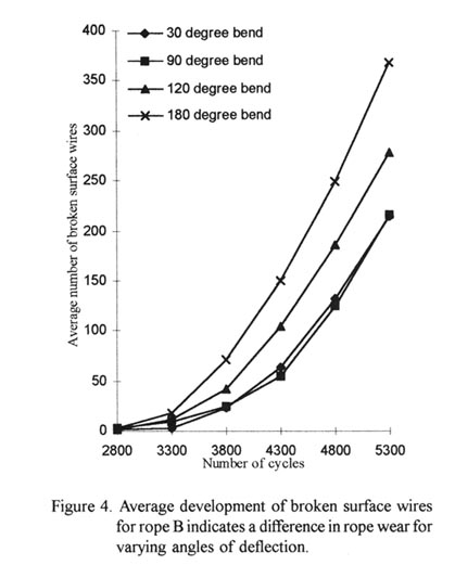
Figure 4: Average development of broken surface wires for rope B indicates a difference in rope wear for varying angles of deflection.
Display large image of Figure 4
DISCUSSION
Validity
The durability of steel wire ropes in cable logging operations depends on the wire rope used, its installation, and its operation. This investigation tested only bending of wire rope on sheaves under constant tension, and its results are therefore valid only under the test conditions used. Many parameters from practical use are left out or simplified, and the test is not directly comparable to the outdoor conditions.
Experimental approach
The calculation of the multiaxial state of stresses of a single wire in a bent wire rope is still not satisfactory, which makes a theoretical approach almost impossible. Since no satisfying answers can be found by theoretical means, they must be clarified experimentally.
Heat accumulation
During the test there were problems with heat accumulation in the ropes. When block axle temperature exceeded 120°C, the test machine was stopped to allow the blocks and rope to cool down. The heat was produced by the rope's inner friction, the ropes rotating on the blocks, and the block bearings. Rope and block axle temperatures were quite similar. The temperature depended on the bending angle; greater angles create higher radial forces in the bearings and, consequently, increase friction.
Due to rope flexing and heating small portions of rope lubricant were deposited on the sheaves. The bearings in the 180° block, which were undersized for the forces applied in the test, collapsed and were replaced twice.
The sheave size
The bending of a wire rope is accompanied by readjustments in the relative positions of the strands and wires. This causes bending of the individual wires in the rope. The fatigue effect of bending appears in the form of small cracks in the wires.
These cracks propagate, under repeated stress cycles, until the remaining sound metal is inadequate to withstand the bending load. This results in broken wires showing no apparent contraction of the ropes cross section area.
Experience has established the fact that from the service viewpoint, a very definite relationship exists between the size of the largest wires of a wire rope and the size of the sheave that it passes over. Sheaves smaller than 200 times the diameter of the largest wires (sheave-rope diameter ratio 13 for A, 16 for B and 17 for C) will cause permanent damage in a heavy loaded rope. Good practice requires the use of sheaves with diameters 800 times the diameter of the largest wires in the rope (Sheave-rope diameter ratio 53 for A, 63 for B and 66 for C) for heavy loaded fast-moving ropes [2].
The formula: D = 200 · δ, where δ is the largest wire diameter in the rope [7], gives a minimum sheave size of 160 mm for A, 200 mm for B and 211 mm for C. The producer recommend a minimum sheave size of 254 mm for B [1]. The sheaves used in the test satisfy the demands for the standard rope, but not the compacted ropes.
Expected lifetime
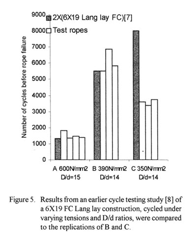
Figure 5: Results from an earlier cycle testing study [8] of a 6X19 FC Lang lay construction, cycled under varying tensions and D/d ratios, were compared to the replications of B and C.
Display large image of Figure 5
Different rope specifications give approximately similar percentage changes in rope life [8]. The endurance of the Lang lay rope (Figure 5) was multiplied with 2 to scale it proportionally to rope A. The testing of the Lang lay rope yields an expected relation between rope A and B that fits well with the test results. Rope C had only half the lifetime compared to the expected relationship with rope A. This indicates that the compaction process has reduced the endurance of rope C for this specific D/d ratio and stress.
Broken surface wires
The broken surface wires developed in narrow paths of fatigue fractures on the compacted ropes. This indicates that the rope has worked in a grossly oversized groove or over a small sheave [9], as was the case in this test. The broken surface wires found by means of visible inspection were of two different types:
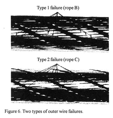
Rope B had only "type 1" wire failures. This is a typical result of bend fatigue [9a]. Rope C had only "type 2 "wire failures, each of which occurred only in one direction and at the same position on the wire. This may be caused by the ropes' heavy compacting process, which results in sharp angles in the wires at these points (Figure 7). These points concentrate the stress and accelerate the fatigue process. The standard rope had both types of failures — type 1 failures where the wires were flattened due to high tread (Hertz) pressure and type 2 failures from interface with adjacent strands.
Figure 6: Two types of outer wire failure.
Display large image of Figure 6
Visible wire failures as an indicator of the rope's strength
In general, the performance of a wire rope is not affected by the occasional broken wire. In a long rope, every wire could be broken somewhere along its length without this causing unsatisfactory performance. There is sufficient friction in the rope to enable a broken wire to develop its total share of the load over a relatively short length.
The problem, however, becomes acute when a number of broken wires occur within a relatively short length of the rope [3]. A problem arises with a method based on fixed test segments when a critical area of failures occurs outside them. In the test described in this article, the number of outer wire failures on the test segments correlated with the compacted ropes' reduction in strength. This may be explained with the relatively long test segments of 12% (Figure 2). Figure 3 shows the linear approximation to the measured values. Rope C had a r2= 0.59 and Rope B had a r2= 0.79.
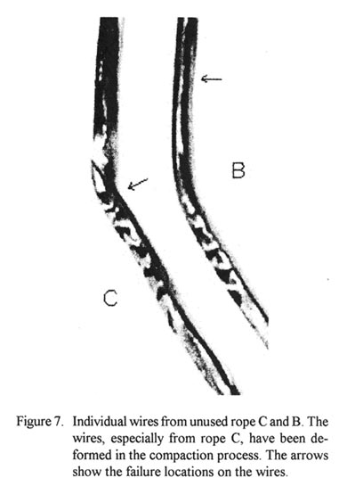
Figure 7: Individual wires from unused rope C and B. The wires, especially from rope C, have been deformed in the compaction process. The arrows show the failure locations on the wires.
Display large image of Figure 7
Two phases of surface wire failure development
The endurance limit for steel — the stress below witch the material can withstand an infinitely large number of stress repetitions — is roughly 50% of its ultimate stress. The more this limit is exceeded, the fewer the stress repetitions the material can be subjected to before failure.
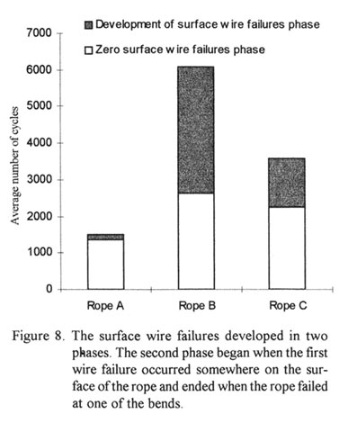
Figure 8 shows two phases of the test cycle, the zero wire failure and the phase wherein wire failure develops. The development phase increases relatively to the zero wire failure phase as the fatigue endurance of the rope construction is raised. After a phase almost free of wire breakage, the development of wire failures increases. The speed at which these develop increases with bigger wire stress and smaller D/d-ratios [4]. However, there must be other influences on rope C, since the exposure to smaller wire stress does not result in a longer failure development phase than rope B. The main difference between Rope B and C is in their degree of compaction. Therefore it is likely that rope C's heavy compaction is to blame for its rapid degradation.
Figure 8: The surface wire failures developed in two phases. The second phase began when the first wire failure occured somewhere on the surface of the rope and eded when the rope failed at one of the bends.
Display large image of Figure 8
The angle of deflection
Figure 4 indicates that the outer wear of rope B depends on the angle of deflection. However, no significant differences were found. Increased bending angles seem to increase the number of surface wire failures. For this test, the number of surface wire failures correlated well to the measurement of the remaining breaking load of the rope (Figure 3). Because of this correlation, figure 4 gives a picture of the total degradation of the rope during the test. Table 2 indicate that the 180° bend was the most critical one for rope B. This fits well with the observed development of broken surface wires for the 180° bend in figure 4. For rope A and C the results indicated wear independent of the angles of deflection.
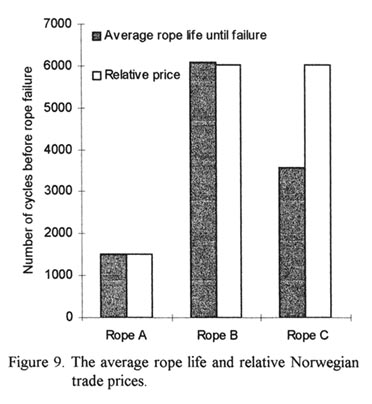
Figure 9: The average rope life and relative Norwegian trade prices.
Display large image of Figure 9
Test results indicated that the Canadian compacted ropes used in Norwegian cable logging are operating on sheaves of insufficient diameters. Sheaves with increased diameter and a groove geometry that fits the rope better may give these ropes longer lives.
Rope B had the longest life in the cycle test (Figure 9). Both lifetime and price were approximately 4 times those of the standard rope.
Of highest importance when selecting a rope is the total economy of the operation, and increased lifetime results in decreased machine downtime. Further, higher density ropes reduce rope crushing and distortion, which improves drum spooling and rope performance. A smooth outer-rope profile reduces wear, increases sheave and drum life, and reduces outer-wire burning (Martensite) from friction [1]. The additional advantages of the smooth outer-rope profile of rope B make it a better choice than rope A.
Results indicate approximately 50% decreased endurance for rope C. This may result from deformation of the individual wires in the production process.
AUTHOR CONTACT
Halvor Torgersen can be contacted by e-mail at --
Halvor.Torgersen@nisk.no
REFERENCES
[1] Brown, R. Correspondence with the manufacturer, unpublished. 5501 Trans Canada Highway, Pointe-Claire, Quebec.
[2] Columbia Steel Company. 1943. Wire rope engineering handbook. The American steel and wire company of New Jersey.
[3] Costello, G. 1997. Theory of wire rope. Second edition. Springer -Verlag New York Berlin Heidelberg.
[4] Feyrer, K. 1994 Drahtseile - Bemessung, Betrieb, Sicherheit. Springer-Verlag ISBN 3-540-57861-7. Berlin, Heidelberg, New York, London, Paris, Tokyo, Hong Kong, Barcelona, Tokyo.
[5] Liley, W.D. 1983. Cable logging handbook. Logging Industry Research Association Inc. Rotorua, New Zealand.
[6] Oplatka, G. and M. Roth. 1981. Equipment for investigating wire ropes used by the Institute for Construction Equipment and Transportation Machinery, Swiss Federal Institute of technology Zurich.
[7] Samset, I. 1985. Winch and cable systems. Martinus Nijoff/ Dr W. Junk Publishers. Dordrecht, Boston, Lancaster.
[8] Scanrope. 1986. Wire rope for engineering. Tønsberg, Norway.
[9] Wire Rope Industries Ltd. 1995. General Wirerope Catalogue. 5501 Trans Canada Highway, Pointe-Claire, Quebec.
[10] Wire Rope Technical Board. 1993.Wire rope users manual. Third edition. P.O. Box 286 Woodstock, Maryland 21163-0286 USA.