
Display large image of Figure 1
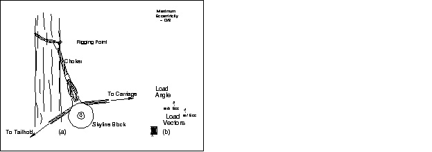
Figure 1. Illustration of a skyline cable yarding system with both intermediate support spar-trees and tail spar-trees.
Vol. 12 No. 2 July 2001
Marvin R. Pyles
Kevin Lyons
Oregon State University
Corvallis, OR
The authors are, respectively, Associate Professor of Forest Engineering and PhD candidate.
Abstract
Unguyed spar-trees are commonly used as a part of skyline cable logging systems. Finite Element Analysis is a robust method for determining spar-tree design load that can include virtually any field condition likely to be encountered. The results of Finite Element Analysis over a range of spar-trees similar in size to those typically found in second-growth Douglas-fir stands indicates that (1) some existing guidelines for use of unguyed spar-trees do not correspond to expected field behavior, and (2) lateral loads of a magnitude found in skyline cable yarding systems dominate the structural behavior of unguyed spar-trees. However, the Euler Buckling load which has been used as a guide to spar-tree capacity, may serve to normalize the results of Finite Element Analysis in such a way that simple linear relationships can be used to estimate spar-tree capacity.
Keywords: Spar-tree, lift-tree, support-tree, cable-logging, design-load, buckling-load, cable yarding, finite element analysis, Pseudotsuga, Douglas fir.
INTRODUCTION
The environmental benefits of skyline cable logging have driven a transition from highlead cable logging to single and multispan skyline logging on steeper terrain in the Pacific Northwest during the past twenty years. The primary environmental benefit derives from the less extensive road system required to support skyline logging relative to shorter span highlead logging. Additionally, there is less overall soil and site disturbance with skyline logging. Skyline logging has also been the system of choice on more gentle terrain where one or more intermediate supports may be required to generate economic payloads. The increased rigging costs associated with most skyline systems generate interest in rigging systems that depart from convention. In particular, loggers may use unguyed intermediate support and tailspar trees in an effort to reduce rigging costs. The desire to use unguyed support trees to reduce rigging costs is always coupled with the necessity of avoiding support tree failures from both an operational and safety perspective. Practical experience has shown that unguyed trees can be used effectively in some cases; however, structural analysis considering large displacements is necessary for defining the limits where they can be used safely.
The objective of this paper is to examine the structural mechanics of an unguyed support tree, present an appropriate analysis for a typical case, and interpret the analysis results in light of conventional standards for spar tree behavior.
BACKGROUND
Skyline logging systems can have a number of different rigging configurations. Each configuration is intended to provide a particular advantage suited to the terrain involved and the logs being yarded. The system illustrated in Figure 1 shows both intermediate support spar-trees and a tail spar-tree. The spar-tree supports are used to increase the lift available in the center and at the end of the overall skyline span respectively. The spar trees may or may not be topped above the rigging point depending on local convention and safety requirements.
Load from the skyline or intermediate support line is applied to the spar-tree through a block that is suspended from the tree by either a choker or a strap (Figure 2a). The choker or strap in combination with the block is intended to operate as a pure tension element such that the directions of the skyline and intermediate support line respectively determine the magnitude and direction of the load on the spar-tree for a given skyline or intermediate support line tension. The geometry of loading illustrated in Figure 2 is such that: 1) the load applied to an unguyed spar tree will rarely, if ever, be in the vertical direction; 2) the load is applied somewhere between the edge of the tree cross section and its center, depending on the exact geometry of the rigging, hence the load will not be axial; and 3) in most cases, the load strap will produce torsion in the tree which can be minimized by careful rigging. The first two factors in combination produce bending moments in the spar tree that in turn produce lateral deflection. This result has been addressed in conventional rigging practices by (1) specifying cases in which guylines are required, and (2) by specifying a maximum lateral deflection of the loaded spar tree at the rigging point [9]. As suggested, torsional loading is addressed by rigging the load strap so as to minimize torsion.
Display large image of Figure 1
Figure 1. Illustration of a skyline cable yarding system with both intermediate support spar-trees and tail spar-trees.

Display large image of Figure 2
Figure 2. Detailed illustrations of (a) a choker
support strap, and (b) the load angle sign
convention and eccentricity used in the analysis.
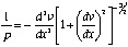
Historically, guidance on the capacity of spar trees has been obtain in the form of the critical buckling load as computed by the classical Euler Equation [6]:
 (1)
(1)
| where: | Pcr =Critical buckling load, E = Modulus of elasticity of the spar tree, I = Moment of inertia of the spar cross section, Le = Effective length of the spar tree (two times the rigging height for an unguyed spar-tree). |
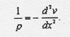
In equation (1), the critical buckling load, is obtained by solution of the linear differential equation of the elastic curve of a column. The linear differential equation is obtained from the more general, non-linear equation by assuming the products of derivatives of small displacements are approximately equal to zero. Formulation of the non-linear equation begins with the assumptions: (1) the column is of constant cross section, and made up of linear elastic material, (2) the column is initially straight, (3) the only load is a compressive load, collinear with the longitudinal axis of the column, and (4) the column itself is weightless. The general non-linear differential equation is:
 (2)
(2)
| where: | ρ = Radius of curvature of the elastic curve, υ = Lateral deflection of the column, χ = Position along the long axis of the column. |
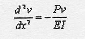
If  , then
  , which reduces equation (2) to:
 (3)
(3)
The axial load in the column is introduced into Equation (3) by using the definition of modulus of elasticity and the bending moment produced by the axial load times the lateral deflection. The resulting differential equation is:
 (4)
(4)
Adaptations to the solution of Equation (4) allow for consideration of a limited number of column end conditions and modest eccentricity of axial load (e.g. Gere and Timoshenko [7]). Column taper and base stiffness can be addressed with a numerical solution (e.g. Carpenter [3]). However, a critical buckling solution to Equation (4) has its limits: (1) it does not allow the determination of post buckling displacements; (2) does not directly address a design stress in the column at which either material non-linear behavior or an unacceptable probability of material failure may occur; and (3) perhaps most importantly, does not consider the effect of the lateral component of the load.
FINITE ELEMENT ANALYSIS
The Finite Element Method (FEM) offers the ability to incorporate virtually any real-world condition into structural analysis. In the case of a tail spar-tree or intermediate support spar-tree, this could include:
1. A cross section that tapers with height,
2. Constant or varying modulus of elasticity as
appropriate,
3. Base stiffness interpreted from tree tests,
4. Load direction consistent with field cases,
5. The effect of load eccentricity and initial curvature,
6. Detail in the modeling that can simulate
continuous behavior, including geometric non-linearity, or the
effect that deflections have on bending moment, and,
7. Interpretation of results in light of a design stress
in the tree.
Tree Taper
For the current study, tree taper was obtained from a taper equation developed by Kozak [8] for second growth Douglas-fir. For any particular field case, a taper equation that best fits the trees in the stand being considered should be selected. We ignored any contribution to structural behavior from the bark. Inside bark diameters at breast height of 30 to 65 cm were considered, these being representative of dominant trees in second-growth Douglas-fir stands. A constant rigging height of 10 m was used, which allowed the spar tree to vary from quite flexible for the smallest diameter tree to quite stiff for the largest diameter. For the current analysis, all spar trees were considered to be topped above the rigging point. This is non-conservative for cases where the trees are not topped.
Modulus of Elasticity
Pyles et al. [12] found that modulus of elasticity (MOE) for standing trees and whole logs from those trees was significantly higher than MOE values from minor specimens sawn from the trees. However, in the interest of linking the current work to a standard value for wood, we elected to use an MOE value of for northern Douglas-fir [1].
Base Stiffness
The base of a tree is neither fixed (infinite stiffness) nor pinned (zero stiffness) but rather, is somewhere in between. Pyles [10] suggested that the stiffness of the base of second growth Douglas-fir trees could be represented by a linear spring with a constant, kbase , (N-m/radian) that is a power function of dbh (tree diameter in meters at breast height):
kbase ,N - m/radian = 23.66 (dbh,m)3.65 (5)
Although we elected to use this relationship, it seems reasonable that local site conditions will influence base stiffness, and therefore may need to be considered.
Load Direction
The load applied to the tree will be in the direction of the load strap (Figure 2a). The direction of the load strap will be in a plane defined by the rigging point, the skyline tail-hold, and the carriage in the case of a tailspar. We elected to consider a range in load angles from a near vertical of 1 degree to 20 degrees from the vertical (Figure 2b). In all cases, it was assumed that tree displacement did not significantly influence strap angle. This is a reasonable assumption since the skyline block serves to equalize the angle of the skyline with respect to the load strap on either side of the block. Deflection of the tree will result in small changes in the load strap angle, but the changes will be much less than one degree in most cases. It was also assumed that the load strap was rigged to eliminate torsion.
Load Eccentricity
An extremely tight choker where the choker line goes around the spar-tree in a horizontal plane, and then "kinks" through the choker bell could produce a load eccentricity near the outer edge of the spar-tree cross section [11]. The more likely case is a load eccentricity somewhere between zero (load at the center of the cross section), and an eccentricity equal to the radius of the cross section. We elected to consider the maximum possible eccentricity (load at the edge of the cross section; see Figure 2b) for a limited number of cases since the lateral load component rather than eccentricity was expected to dominate spar-tree behavior. Load eccentricity can also result from initial curvature of the tree; however, we considered only straight trees in this general analysis.
FEM Element Type and Number
Different levels of sophistication have been used in FEM modeling of trees. The level of sophistication required depends on the objectives of the analysis. In analysis of guyed spar trees that considered the path dependant loading produced by sequential tightening of the guylines, Ammeson et al. [2] used simple beam elements. Ammeson et al. [2] incorporated tree taper by changing the cross section of the elements with height, but MOE was held constant. In contrast, Franco and Pellicane [5], who were attempting to predict the failure point on a tree given defects observable on the surface, used a detailed solid element model that allowed them to consider the grain angle and anisotropy. Our analysis used the commercial FEM package by ANSYS©. We selected a simple three dimensional beam element with isotropic properties (the ANSYS© Beam 4 three dimensional elastic element) for the current study based on the work by Conner [4] who used a similar element to study guyed spar tree behavior. This element has two nodes with six degrees of freedom at each node. An option for a third node used for orientation of the element was not used because the tree cross sections were assumed to be circular, and therefore symmetric. Based on the work of Ammeson et al. [2], 10 beam elements were used to model the tree. The individual element cross sections were constant, but the element to element cross sections varied to simulate tree taper in the same manner as Ammesom et al. [2]. The deadload produced by the weight of the spar tree was not included in the analysis because live loads were expected to be dominant. Large displacements, expected as a result of lateral load components were considered. ANSYS© uses the Newton-Raphson method to model geometric non-linearity in the system.
Interpretation of FEM Analyses
Interpretation of the FEM results was done from the perspective that the maximum design load on the tree from the load strap is limited by the design compressive stress for the tree. The design tension for the load strap is defined as the tension in the load strap that will produce a compressive stress on a transverse cross section, at some point in the tree, which is equal to the design compressive stress for the tree. For the analysis performed here, the value selected as the design stress for the tree must be within the linear elastic range. The National Design Specification [1] value for allowable stress in bending for northern Douglas-fir (1.103*104 kPa) will be used as the design stress for the tree in this analysis. No adjustment was made for duration of load or the other factors that are normally considered in design of buildings and other civil structures. The dominant factors in this case, column stability and geometric nonlinearity (bending stress amplification), are explicitly considered in the analysis. Both static and dynamic loads on cable logging systems are of short duration with respect to normal load duration for which the National Design Specification values have been developed. Short duration of load normally corresponds to increases in allowable stress, hence, with respect to duration of load, our interpretation should be conservative.
For convenience, the FEM input parameters are summarized in Table 1.
Table 1. Parameter values used in the FEM analysis.
RESULTS
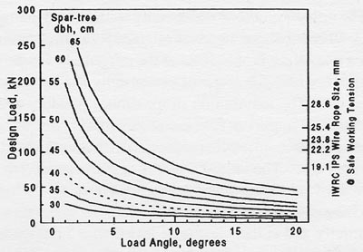
Direct results of the analysis showed the importance of the horizontal load component and the degree to which tree displacement at the rigging point might be considered as a performance criteria for safe spar trees. Figure 3 shows the computed design load based on reaching the design stress in the wood of the spar tree for the eight tree diameters analyzed as a function of load angle. The minimum line size required for the design tension has been included as a second ordinate on the right hand side of Figure 3. The required line size was determined from the safe working tension (one-third the nominal breaking strength) reported by the Workers Compensation Board of British Columbia [13] for improved plow steel (IPS). This second scale can be read directly as choker size if a choker is used to hang the block in the spar-tree (Figure 2a). The dramatic influence of the lateral load component is evident in Figure 3. Even a modest 5 degree load angle reduces the design choker tension to about half of the value at a 1 degree load angle. Interpretation of the results in Figure 3 beyond the line size scale is difficult due to the wide range in field conditions and operation modes that can occur. However, the range of values in Figure 3 do provide results that can easily be compared to the loads likely to be generated for many yarding and rigging configurations.
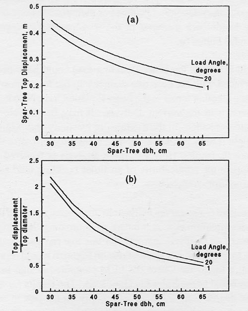
Lateral deflection at the rigging height when the tree has been loaded to the maximum design stress in the wood is shown as both an absolute value (Figure 4a) and normalized as a multiple of spar tree diameter at the rigging height (Figure 4b). The values for only the extreme load angles are shown in Figure 4.

Display large image of Figure 3
Figure 3. Computed design spar-tree load (support
strap tension) as a function of load angle and spar=tree diameter at breast height.
The computed displacement at the rigging height for the smallest tree (30 cm dbh; 20.7 cm diameter at the 10m rigging height) was between 0.42 and 0.45 m depending on strap angle, or just over 2 times the tree diameter at the rigging height. The computed displacement at the rigging height for the largest tree (65 cm dbh; 40.7 cm diameter at the 10m rigging height) was between 0.19 and 0.23 m depending on strap angle, or about half of the tree diameter at the rigging height. It is clear from Figure 4 that neither a fixed displacement at the rigging height, nor a rigging height displacement expressed relative to spar-tree diameter can describe both a safe performance condition and the deflection that corresponds to the design load for unguyed spar trees.

Display large image of Figure 4
Figure 4. Computed spar-tree rigging-height
displacement at design load for a range in spar-tree
sizes (a) in absolute measure, and (b) relative to
spar-tree diameter at the rigging height.
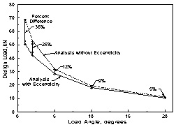
The influence of load eccentricity is illustrated in Figure 5. A 40 cm dbh spar-tree was selected for the comparison since it is on the flexible end of the range used for the full analysis, where the effect of eccentricity should be quite apparent. The assumption of maximum possible eccentricity, load application at the edge of the cross section, produced a 5 to 36 percent reduction in the design load for the spar-tree. The largest reductions corresponded to the smallest load angles where lateral load does not dominate the behavior. Rigging so as to produce the maximum eccentricity and at the same time less than a 5 degree load angle for all yarding cases for a particular spar-tree seems unlikely, hence the effect of eccentricity is probably less than 10 percent for the critical load case.
Design Load Relationship
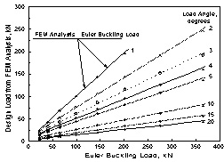
Figures 3 and 4 show systematic behavior as should be expected for spar trees that vary only in diameter. The illustrated behavior indicates that the critical buckling load computed from the Euler Equation is not an appropriate measure of the capacity of unguyed spar trees, however, the desire to have a relatively simple method for estimating spar tree capacity remains. A suggestion for such an approach can be found in the results presented in Figures 3 and 4. The design loads for each strap angle are a nonlinear function of spar tree diameter at breast height. However, the design strap load relationship has a nearly linear relationship over the range of interest with the critical buckling load computed by the Euler Equation for fixed-base, unguyed columns with a constant diameter equal to the inside bark diameter of the spar-tree at the rigging height (Figure 6).
In Figure 6, the Euler Buckling load could have been replaced with the spar-tree diameter to the fourth power since all other terms in the Euler Equation have been held constant in the current analysis. It may be possible to address changes in the modulus of elasticity and rigging height if the Euler buckling load is used to normalize the analysis results. However, more analysis is required to confirm the applicability of an Euler buckling load as a normalization term.
Figure 6 also serves to illustrate the degree to which the Euler equation errs as a means of estimating the design load of an unguyed spar-tree. A line that passes through the origin and has a slope of one on Figure 6 would represent a load case where the FEM computed design load was equal to the Euler buckling load. The results for the one-degree load angle are essentially on the one to one line, but the results for all other load cases are significantly below the Euler buckling load.

Display large image of Figure 5
Figure 5. Effect of load-connection eccentricity for a
40 cm dhb spar-tree as a function of load angle.

Display large image of Figure 6
Figure 6. Linearization of the computed design load
relationships by the Euler Buckling Load.
CONCLUSIONS
Unguyed spar-trees have been used successfully in numerous cases in practice. There is clearly a range of spar sizes and rigging heights where the spar will have adequate capacity for a safe and efficient yarding operation. Safety codes have attempted to identify this range by listing limitations on the use of unguyed spar-trees. Euler buckling analysis has been suggested as a guide to the capacity of unguyed spar-trees, but the analysis presented here indicates that Euler buckling calculations do not adequately represent the structural behavior of unguyed spar-trees. FEM analysis is the preferred method for analyzing unguyed spar-trees because the true field geometry and spar characteristics can easily be incorporated into the analysis. However, FEM analysis requires considerable computational effort, and does not remove the desire for simple, easy to use guidelines. A suggested form for such a guideline has been presented here, but additional analysis will be required over a broader range of field conditions before a final guideline can be achieved. Notably, a full range in stand conditions that will affect the taper and possibly base stiffness of the trees should be examined. While the range in spar diameters at constant rigging height produced a range in spar stiffness (or slenderness ratios), it is not clear that all aspects of spar stiffness have been identified.
AUTHOR CONTACT
Dr. Pyles can be reached by email at --
marvin.pyles@orst.edu
References
[1] American Forest and Paper Association. 1997. National Design Specification (NDS), Supplement for wood construction, American Forest and Paper Association, American Wood Council.
[2] Ammeson, J.E., M.R. Pyles, and H.I Laursen. 1988. Three-Dimensional Analysis of Guyed Logging Spars. Computers & Structures, 29(6):1095-1099.
[3] Carpenter, S.T. 1960. Structural Mechanics. John Wiley & Sons, New York. 538p.
[4] Conner, G.F. 1989. Comparison of Field-Test and Computer-Model Results for a 3-D Guyed Logging Spar. Master of Science Engineering Report, Department of Civil Engineering, Oregon State University, Corvallis, OR. 92p.
[5] Franco N. and P. Pellicane. 1993. Three-Dimensional Model for Wood-Pole-Strength Predictions. J. Struct. Eng., 119(7): 2199-2214. [6] Garland, J.J., D.D. Studier, and C.J. Hoefer. 1986. Logging Planning with the Hewlett-Packard 41-C Series Calculator. Forest Research Laboratory, Oregon State University, Corvallis, OR. 151p.
[7] Gere, J.M. and S.P. Timoshenko. 1984. Mechanics of Materials. PWS Publishers, Boston, MA. 762p.
[8] Kozak A. 1988. A variable-exponent taper equation. Can. J. For. Res., 18(11): 1363-1368.
[9] Oregon Occupational Safety & Health Division (OR-OSHA). 1992. Oregon Occupational Safety and Health Code, Oregon Administrative Rule, Chapter 437, Division 6, Forest Activities. Department of Consumer & Business Services, Salem, OR. 126p.
[10] Pyles, M.R. 1987. Structural Properties of Second-Growth Douglas-Fir Logging Spars. Transactions of the ASAE, 30(1): 65-69.
[11] Pyles, M.R., Pugh E.V. 1987. Two-Dimensional Analysis of Logging Tail Spars. For. Sci., 33(4): 971-983.
[12] Pyles, M.R., J.E. Ammeson, and J.W. Mann. 1988. The flexural behavior of second-growth Douglas-fir spars. For. Prod. J., 38(5): 58-62.
[13] Worker Compensation Board of British Columbia. 1993. Cable Yarding Systems Handbook. Worker Compensation Board of British Columbia, 175p.