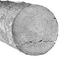
Figure 1. A typical example of an end check at the end of the log. [8]
Vol. 13 No. 1 January 2002
Juha Inberg
Jouni Mattila
Tapio Virvalo
Tampere University of Technology
Finland
ABSTRACT
The cutting function is an essential part of a harvester's work in the cut-to-length method. The quality of cutting is the most significant feature of a cut. Trees should be cut without causing damage to logs produced. Nowadays end checks of logs are the main problem in the cutting process. It has been observed that end checks are found in as many as 70% of the logs produced by harvesters. Cutting damage reduces the amount of useful material and causes considerable economical loss to the sawmill and veneer industries.
This study presents a theoretical background for the boom-lowering function, which is one solution to avoid cutting damage during the timber cutting process. The purpose is to momentarily counterbalance the gravitational force of the log in horizontal timber cutting. The study discusses the feasibility of controlling the boom tip in the vertical plane during the cut. In this study the boom tip motion trajectory along the g-vector is modelled for both one and two linear actuators. On the basis of this theoretical study, it seems that acceleration of one g is possible to realise with certain improvements in hydraulics. However, experimental measurements are required to verify these theoretical results. This will include the more detailed study of the effects of deceleration limits on boom stability.
Keywords: Cutting control, boom control, timber cutting, cross-cutting, cut-to-length harvester, backing, shortwood, log end checks.
The authors are, respectively, Researcher, Senior Researcher, and Professor at the Institute of Hydraulics and Automation.
INTRODUCTION
Nowadays a great deal of final felling in the cut-to-length method is done by single-grip harvesters. Cutting trees is an important part of a harvester head operation. In single-grip harvesters, trees are cut with hydraulically driven chain saws. Trees are expected to be cut without causing longitudinal splits in the end of the log. Although the timber cutting process is quick, cutting damage is a serious problem in today's forestry. It has been observed that cutting damage is found in as many as 70% of the logs [6]. The most significant cutting damage is the end check (Figure 1), which will appear when the tree is supported by the harvester head and the log to be cut is hanging freely. The gravitational force of the log causes bending torque to the cutting point. The bending creates high stresses on the wood, and these stresses will cause the log to split before the log has been cut off. Damage resulting from the cutting process reduces the amount of useful material and cause considerable economic loss to the sawmill and veneer industries.
For a long time, operators have tried to manually counterbalance the gravitational force of the log to be cut manually by accelerating the boom downward during the final stage of the cut. But this requires great skill, and if it is done at a wrong time it causes even more damages. For a couple of years the manufacturers of harvester machines have worked with this problem to automate the operation. In some modern single-grip harvesters the boom and thus harvester head is accelerated downward automatically during the final stage of the cut [8]. It is important that this technique be done carefully and just at the right time in order to lessen the torque on the log as it is being cut to length. The purpose is to get the harvester head and the log to fall at the same acceleration during the cut. Therefore proper timing, duration, falling acceleration and deceleration are very important parameters in achieving the desired result.
Figure 1. A typical example of an end check at the end
of the log. [8]
Cut-to-length technology was first introduced in Scandinavia and today this method of harvesting trees has gained acceptance and is becoming common in other continents as well. The frequency and effects of end checks are studied in several publications [3,6,10]. Also some basic guidelines, how the checks could be avoided are given by Skogforsk [4, 5, 9]. However, the theoretical background for the boom acceleration control has not been presented before and, therefore, the objective of this paper is to supplement the theoretical background of this technique. This paper analyses the performance of the boom lowering function and discusses the feasibility of this technique to control the boom tip in the vertical plane during the cut. In this study the boom tip motion trajectory along the g-vector is implemented with two linear actuators. Boom motion with one actuator is also considered. This study is based on a kinematics analysis of a boom used on a Ponsse single-grip harvester.
HORIZONTAL TIMBER CUTTING
In horizontal timber cutting, the tree is cut without a support, and the gravitational force of the log causes bending torque to the cutting point before the tree has been cut off. Figure 2 describes the situation how the log starts to bend when the chain has gone deep enough and the log is going to crack.
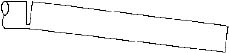
Figure 2. The situation when the log is going to crack.
The effect of the gravitational load force can be counterbalanced if the harvester head is moved so that the gravitational force of the log can be compensated. To control the boom movement during the cut, the controller needs information about the cutting process. The feedback in boom control is based on the log dimensions and the bar position as well as on the permissible travelling distance of the movement. The starting time of the boom tip acceleration depends on how much the tree can bend without a first crack, and also on the delay of the system. The duration of action has to be long enough so that the whole tree is cut before the deceleration begins.
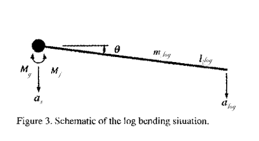
A schematic of the log bending situation is shown in Figure 3. The log is assumed to be a rigid, thin rod, which has the mass of mlog and the length llog. The total torque, which affects the cutting point, can be described by
Mtot = Mg - MJ
(1)where Mg is the gravitational torque caused by the log and MJ is the inertial torque of the log. The gravitational torque is defined as
where g is the magnitude of the gravitational acceleration. The inertial torque for the log can be described by
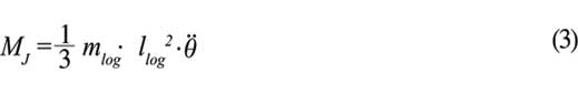
where is the angular acceleration of the log. The acceleration alog of the free end of the log can be written as follows
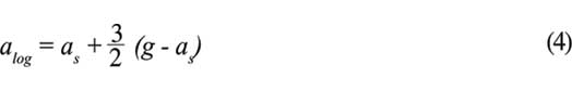
where as is the acceleration of the support element, in this case the acceleration of the harvester head. For instance, if the harvester head has the acceleration of g during the cut, it follows that the acceleration alog is also g. If the harvester head is in rest position, just before the log has been cut off the tree starts to bend, yielding the acceleration of 1.5 g to the free end of the log. However, the purpose is to keep the angle q as close to zero as possible during the whole cut. Therefore the boom tip acceleration should begin before the log is going to bend.
RESULTS
The schematic drawing of the commercial boom studied is shown in Figure 4. It has an reach of 9.5 m and lifting capacity of 2500 kg (at 5 m). The system studied has four degrees of freedom (DOF), which are the rotation movement of the boom base and three DOF's for plane motion. In this study only the plane motion of the boom with two actuators z1 and z2 is considered. The kinematics equations for the boom studied are derived in Appendix A.
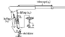
Figure 4. The studied harvester boom.
The desired acceleration motion profile for the boom
tip position has the magnitude of g along vertical plane
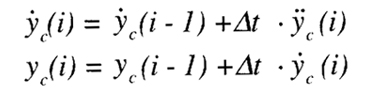
downwards. The velocity and position trajectories of the
boom tip are calculated from the desired g-vector
acceleration trajectory  . The boom tip is moving from initial
position to final rest position in a given time. The initial velocity
is equal to zero. The velocity
. The boom tip is moving from initial
position to final rest position in a given time. The initial velocity
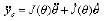
is equal to zero. The velocity  and position
yc vectors can be calculated as follows:
and position
yc vectors can be calculated as follows:
 (5)
(5)
where  is the time period between two consecutive
acceleration values.
is the time period between two consecutive
acceleration values.
The calculations are carried out at four different acceleration times: 0.2, 0.3, 0.4 and 0.5 seconds, while the deceleration time is assumed to be 0.2 seconds in each case. In the calculations the total length of link L23 (see Appendix A) is set to 6.0 m. Figures 5, 6, and 7 show the trajectory generations at the boom tip, in which the trajectories at 0.5 seconds acceleration time are shown. In other words, the switching from maximum acceleration to maximum deceleration occurs at the time of 0.5 seconds. As can be seen the velocity at the boom tip increases up to almost 5 m/s, and it drops when deceleration starts, yielding the total travelling distance of 1.7 m at the boom tip.
BOOM CONTROL WITH TWO ACTUATORS
The purpose is to move the boom tip downwards along the g-vector in Cartesian space using two actuators; z1 and z2. Figure 8 shows the boom initial and end positions after an action. The uppermost boom posture describes the initial position and the next four postures are the final positions at four different acceleration times. The circle at the end of the boom describes the harvester head. In this case, the time of 0.5 seconds is almost the maximum, as a longer acceleration time would cause the harvester head crashing to the ground.
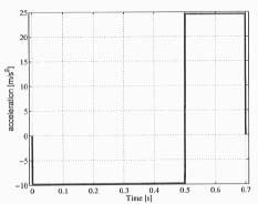
Figure 5. Boom tip acceleration trajectory.
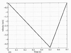
Figure 6. Boom tip velocity trajectory.
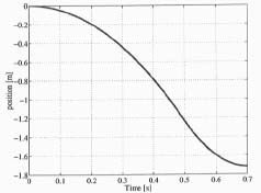
Figure 7. Boom tip position trajectory.
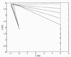
Figure 8. Boom position before and after an action at different acceleration times.
Figure 9 shows the positions of actuators z1 and z2 at different acceleration times as a function of time. The upper curves describe the position of z2 and lower curves the position of z1. According to this figure the actuator z2 is the main movable actuator when the boom tip is moved along the g-vector in Cartesian space.
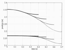
Figure 9. Acturator positions at different acceleration times.
Figure 10 shows the actuator velocities and at different acceleration times. The maximum velocity of the actuator z2 grows up to 0.45 m/s, when acceleration time is 0.5 seconds. The acceleration time of 0.2 seconds yields the maximum velocity; almost 0.2 m/s. At small acceleration times, the velocity of actuator z1 is quite small, but at 0.5 seconds it reaches almost 0.25 m/s.
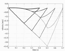
Figure 10. Acturator velocities at different acceleration times.
Figure 11 shows the oil volume flow from the cylinders during an action. The upper curves show the flow rate of cylinder z2. The flow rate increases as a function of time and is over 400 l/min at 0.5 seconds. The maximum flow rate for z1 is about 100 l/min. Normally the maximum flow rate in boom hydraulics is about 200 l/min. Therefore the flow rates shown in Figure 11 are not realistically achievable without a modification of the hydraulic system.
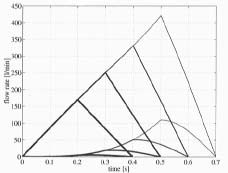
Figure 11. Oil volume flows at different acceleration times.
BOOM CONTROL WITH ONE ACTUATOR
When two actuators were used it was seen that the actuator z2 is the main one during the action. This is also the actuator which is used by the driver when he lowers the boom manually during the cut. When only one actuator is used, the boom tip moves along a circle. The boom tip has the acceleration of g along the y-vector in a vertical plane. The corresponding results are shown in Figures 12, 13, and 14. Figure 12 shows the boom initial and end positions at four different acceleration times: 0.2, 0.3, 0.4 and 0.5 seconds. The initial position is the same as in Figure 8. Figure 13 shows the position of actuator z2 at different acceleration times as a function of time. The total displacement of the actuator z2 is almost 150 mm. Figure 14 presents the actuator velocity z2 as a function of time.
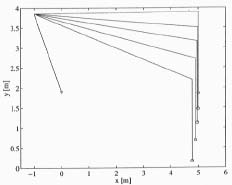
Figure 12. Boom position before and after action at
different acceleration times.
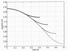
Figure 13. Actuator position at different acceleration times.
However, the use of only one actuator causes also
the horizontal acceleration to the log. This situation is
shown in Figure 15, in which the horizontal (upper curves)
and vertical (lower curves) velocities of the boom tip are
shown as a function of joint angle
 (see Appendix A). The horizontal velocity increases as a function of joint
angle and reaches almost 1 m/s at 0.5 seconds
acceleration time, when the deceleration begins. The horizontal
velocity of 1 m/s corresponds the horizontal acceleration of
2 m/s2 at the boom tip. To avoid the horizontal
acceleration in the log, at least two actuators should be used
simultaneously.
(see Appendix A). The horizontal velocity increases as a function of joint
angle and reaches almost 1 m/s at 0.5 seconds
acceleration time, when the deceleration begins. The horizontal
velocity of 1 m/s corresponds the horizontal acceleration of
2 m/s2 at the boom tip. To avoid the horizontal
acceleration in the log, at least two actuators should be used
simultaneously.
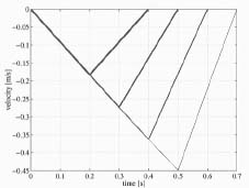
Figure 14. Actuator velocity at different acceleration times.
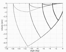
Figure 15. Boom tip velocities at different
acceleration times as a function of joint angle
BOOM TIP DECELERATION
The magnitude of the required deceleration of the boom tip depends on the maximum velocity and the time in which the movement will be stopped. The theoretical decelerations at different acceleration and deceleration times are shown in Figure 16. The acceleration time of 0.5 seconds with deceleration time of 0.1 seconds yields the maximum deceleration of 5 g.
In practice, the maximum deceleration is limited by two factors. Firstly, the maximum system pressure is limited by a pressure relief valve between the cylinder chamber and the valve. The pressure is not able to arise above the set value of the pressure relief valve and therefore the hydraulic system limits the magnitude of maximum deceleration. Secondly, the stability of the harvester machine limits the magnitude of maximum deceleration. The machine is not allowed to fall, even not to cause any damage to the structure of the machine. Machine stability is influenced by the orientation and weight of the base machine as well as the orientation and the load of the boom. Therefore, the orientation of the boom as well the base machine should be known and this information could be processed in electronic control unit to define the initiation of the boom downward movement and also the maximum permissible magnitude of deceleration.
Figure 17 presents the maximum deceleration as a
function of joint angles  and
The deceleration magnitude of 2.5 g is marked by a plain surface to denote the
deceleration limit used in this study. According to this
figure, the deceleration magnitude of 2.5 g is achievable in
certain boom orientations. The opening pressure of the
pressure relief valve is set to 21 MPa.
and
The deceleration magnitude of 2.5 g is marked by a plain surface to denote the
deceleration limit used in this study. According to this
figure, the deceleration magnitude of 2.5 g is achievable in
certain boom orientations. The opening pressure of the
pressure relief valve is set to 21 MPa.
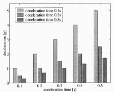
Figure 16. Deceleration of the boom tip as a function
of acceleration and deceleration times.
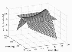
Figure 17. Maximum deceleration of the boom tip as
a function of joint angles.
OBSTACLE AVOIDANCE
In harvester work the workspace is limited and the distance from the boom tip to the ground is typically a couple of meters. Figure 18 presents the maximum acceleration time as a function of distance to the ground at four deceleration magnitudes. This information can be used in predicting the initiation of the boom downward movement.
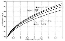
Figure 18. Acceleration time as a function of distance
to the ground at four deceleration magnitudes.
SUMMARY AND DISCUSSION
The objective of this study was to define the requirements that boom hydraulics should satisfy. To counterbalance the gravitational load force in horizontal timber cutting, the magnitude of the acceleration in the boom tip should be as close to g (9.81 m/s2) as feasible. The effect of the magnitude of the acceleration on the actuator velocities and thus oil volume flows in hydraulic system was studied in this paper. The maximum flow rate in the system was calculated based on the kinematics model of the studied harvester boom. From the practical point of view, most interesting are the maximum flows, because the hydraulic system has be to be designed and dimensioned based on the maximum flow in the system.
To follow g-vector motion trajectory, oil volume flow grows over 400 l/min. This flow rate is, however, not realistically achievable without a modification of the hydraulic system. When the oil volume flow increases, pressure losses in valves and conduits grow significantly causing the force to resist the free falling of the harvester head and the log. The most usable alternative is to modify the hydraulic system so that pressure losses in valves and conduits are reduced. In the system studied this requires replacement of the current valves. While the tendency is to use mobile valves for this application, further empinical studies are needed to show whether this is possible.
The deceleration should be smooth enough that it does not cause the machine to fall nor to sustain any damage to its structure. In addition to stability, the magnitude of the deceleration should not weaken the ergonomics of the operator working conditions. The magnitude of the maximum deceleration is limited also by the maximum system pressure, set by the pressure relief valve between the cylinder and the valve chamber. Feedback from the orientation of the boom and the base machine could be used to define the maximum magnitude of the deceleration.
This study was done with only one initial orientation of the harvester boom studied. From the practical point of view, this initial position may be quite impractical according to harvester operators. In practice, drivers typically cut the trees closer to the ground. After the cut the harvester head has to be lifted to the same initial position. Because of this additional lifting movement, the effective working time decreases. The longer the movement, the more time the action requires.
CONCLUSIONS AND FURTHER STUDIES
In further studies, a dynamic model for the boom will be developed. The model will be used to examine the influence of boom position and hydraulics with different loads on boom tip acceleration performance. The dynamic model will also be used to develop a control system to achieve both efficient and smooth boom control. Determining the right time to start the boom acceleration remains very important because of limited workspace and thus the limited acceleration time. The right starting time depends especially on parameters such as; the angle, how much the tree can bend without the first crack, whether the checks behave similarly with different woods, and how the dimensions of log influence the cracks. When these parameters are known, the proper boom control, together with the faster cutting process, are the main factors in achieving cutting without end checks.
REFERENCES
[1] Beiner L. and Mattila J. 1999. An Improved Pseudoinverse Solution for Redundant Hydraulic Manipulators. Robotica (17):173-179.
[2] Craig J. 1989. Introduction to Robotics: Mechanics and Control. 2nd edition. Addison-Wesley Publishing Co.
[3] Eronen, J., A. Asikainen, J. Uusilalo and L. Sikanen. 2000. Control of Log End Checks during Bucking with a Modified Single-Grip Harvester. For. Prod. J. 50 (4):65-70.
[4] Hallonborg, U. and Granlund, P. 1999. Correct Technique Reduces Bucking Splits. Skogforsk Resultat Nr. 19/1999. 4 p. (in Swedish).
[5] Hallonborg, U. and Nordén, B. 1999. Supporting Stems during Bucking Reduces Splits and Is Profitable - Despite Lower Productivity. Skogforsk Resultat Nr. 11/1999. 4 p. (in Swedish).
[6] Helgesson T. 1997. Förekomst av Kapsprickor hos Sågtimmer Upparbetat med Skördare (Occurence of End Checks in Logs Caused by Single-Grip Harvester). Trätek Report P 9712100 27 p. (in Swedish).
[7] Mattila J. and Virvalo T. 1998. On Energy-Efficient Motion Control of a 3 DOF Hydraulic Crane with Computed Force Control Method. 1st International Conference on Fluid Power, Aachen, Germany.
[8] Ponsse Oyj. 2000. Design Manual CD.
[9] Skogforsk. 2000. Ett Skott är för Mycket - Att Motverka Kedjeskott. Handledningen. (A shot is too much -- to prevent chain breakage. Handbook.) Skogforsk, Stiftelsen Skogbrukets Forskninginstitut, 25 p. (in Swedish).
[10] Westerlund M. 1999. Occurrence and Length of Cracking in Spruce, Caused by Single-Grip Harvesters. Students' Report Nr. 26. Swedish University of Agricultural Sciences, 13 p. (in Swedish).
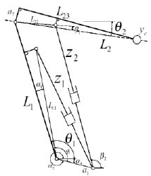
KINEMATICS OF THE FOREST BOOM STUDIED
The free body diagram of the studied boom is shown
in Figure 1. Hydraulic cylinders z1 and
z2 drive two links L1 and
L2. However, two cylinder ends are connected to
the common fixed point and, therefore, the joint angle
is dependent on the strokes of both cylinders
z1 and z2.
In Figure 1 the variables are
z1, z2, ,
, q1 and ß2. In
this paper, the length L23 and thus
L2 are constant. In the experimental system only hydraulic cylinder positions
z1 and z2 are measured, from which joint angles
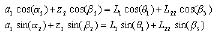
q1 and q2 are calculated. The position of the boom Cartesian tip is
defined as
 (1)
(1)
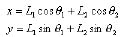 (2)
(2)
Equation (2) can be written in a more compact form
 (3)
(3)
Thus the Cartesian velocity and the acceleration of the boom tip are obtained as follows
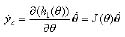 (4)
(4)
 (5)
(5)
where J denotes the Jacobian of the joint-to-Cartesian transformation.
In the inverse kinematics problem of the boom, the boom tip Cartesian position is given, and corresponding joint angles have to be solved
 (6)
(6)
Solution to this 2-DOF problem can be found from
most of the robotics books [2] and is not presented here.
For solved joint angle values and
, the actuator positions
z1 and z2
are calculated. The angle
depends only on actuator position
z1 and therefore the calculation of
z1 as a function of
is straightforward, and it follows that [1,7]
 (7)
(7)
 (8)
(8)
A four-bar structure
L1-a1-z2-L
22 has to be solved to obtain
z2, which is a function of both joint angles
and . To the four-bar structure the following loop Equation
can be written
 (9)
(9)
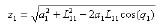
Eliminating ß2 and solving for z2 Equation yields
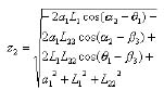 (10)
(10)
where ß3 can be written as follows
 (11)
(11)
Equations (7) and (10) can be rewritten in a more compact form
 (12)
(12)
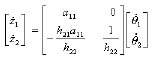
Differentiating Equation (12) twice gives
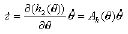 (13)
(13)
 (14)
(14)
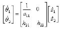
where Ah denotes the Jacobian of the joint-to-actuator transformation. Direct differentiation of (7) gives
 (15)
(15)
where
 (16)
(16)
However, in calculation of time derivatives of z2, it is beneficial to use complex notation for vectors as follows
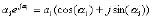 (17)
(17)
By using Equation (17) to convert loop Equations in (9) to complex form, differentiating the result with respect to time, and eliminating will result in an Equation
 (18)
(18)
where
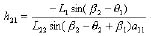 (19)
(19)
 (20)
(20)
Converting Equations (18) and inverse of (15) into vector form yields
 (21)
(21)
Inverting the Equation in (21) yields to the following form
 (22)
(22)
The desired Ah in Equation (13) can now be rewritten in the simplified form
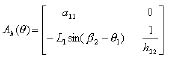 (23)
(23)
Therefore, it follows that velocities from Cartesian-to-actuator coordinates can be written in the following short hand notation
 (24)
(24)