FEATURE
Igneous Rock Associations 6.
Modelling of Deep Submarine Pyroclastic Volcanism: A Review and New Results
W. S. DowneyDepartment of Geology, University of New Brunswick, PO Box 4400, Fredericton, New Brunswick, Canada E3B 5A3
warna.downey@unb.ca
D. R. Lentz
Department of Geology, University of New Brunswick, PO Box 4400, Fredericton, New Brunswick, Canada E3B 5A3
Accepted as revised 08 February, 2006
SUMMARY
Deep submarine explosive volcanism has been a topic of controversy for over 20 years. The role seawater pressure plays in inhibiting volatile phase expansion and thereby the depth of submarine explosive eruptions has been the topic of rigorous debate. Until now, the water-vapour curve has been interpreted to mean that the pressure exerted by the overlying seawater column is significant enough to inhibit explosive volcanism at depth. This interpretation assumes that pyroclastic eruptions cannot occur below the critical point of seawater (31.5 MPa or 3.15 km water depth) in the region of the two phase liquid-vapour fields. In fact, most eruptions are interpreted to occur at depths much shallower than 3.15 km, i.e., 0.5 to 1.0 km. What has been overlooked, however, is that volatile phase expansion (specific volume changes in P-T space) plays an important, if not dominant, role in explosive eruptions at depths greater than this critical point. This controversy has led to debate on the environment of formation of volcanic massive sulfide deposits (VMS), because "pyroclastics" are recognized in both the footwall and (or) hangingwall sequences of many of them and are commonly interpreted as reworked, mass-flow deposits from shallow water rather than of deep-water origin, i.e., they have no genetic relationship with the formation and distribution of VMS deposits. To evaluate the possibility that submarine eruptions can occur at depths greater than 1 km, the 1-D numerical model CONFLOW was used. This program uses a specified melt composition, conduit diameter and length, and the initial temperature and pressure at the base of the conduit to calculate the pressure gradient in a conduit of constant cross-sectional area, the enthalpy of the magma, the viscosity of the volatile-magma mixture at specified P-T conditions, the fragmentation depth where the volume fraction gas is 75% (vg ≌ 0.75), and the exit velocity of the volatile-magma mixture. Results of the CONFLOW modelling support our hypothesis that magmatic volatile phase expansion is alone capable of providing enough energy and high enough melt/gas ratio, to initiate submarine pyroclastic eruptions in silicic magmasto the water depths typically associated with VMS genesis, i.e., below the two-phase (liquid-vapour) region for seawater.RÉSUMÉ
Le volcanisme sous-marin explosif a été l'objet de controverse pendant plus de vingt ans. Le rôle inhibiteur de la pression de l'eau de mer, et donc de la profondeur d'eau, sur l'expansion de la phase volatile des éruptions sous-marines explosives a été l'objet d'un rigoureux débat. Jusqu'à maintenant, on a supposé que l'interprétation de la courbe de pression de vapeur d'eau permettait de croire qu'à partir d'une certaine profondeur, la pression de la colonne d'eau de mer était suffisamment importante pour inhiber le volcanisme explosif sous cette profondeur. Cette interprétation implique qu'il ne peut y avoir d'éruptions pyroclastiques en merà partir d'une profondeur critique (31,5 MPa ou 3,15 km de profondeur) dans la région de la courbe où coexistent les phases liquides et gazeuses. De fait, dans la plupart des cas, on suppose que les éruptions se produisent à des profondeurs bien inférieures à 3,15 km, soit entre 0,5 et 1,0 km. Cependant, on a négligé le fait que l'expansion de la phase gazeuse (le volume spécifique change dans le domaine P-T) joue un rôle important, voire déterminant, dans le phénomène des éruptions explosives aux profondeurs dépassant la profondeur critique. Cette controverse a entraîné un débat sur milieu de formation des gisements de sulfures massifs volcanogéniques (SMV), étant donné qu'on retrouve des les séquences de roches pyroclastiques de l'éponte inférieure et/ou de l'éponte supérieure de nombreux gisements SMV, l'interprétation générale voulant qu'il s'agisse de gisements de mouvement de masse remaniés en milieux peu profonds, plutôt que de milieux profonds - une interprétation qui exclue toute relation génétique concernant la formation et la distribution des gisements SMV. Dans le but d'évaluer la possibilité que des éruptions sous-marines puis-sent se produire à des profondeurs dépassant 1 km, on a eu recours au programme de modélisation numérique 1D CONFLOW. Ce programme permet de tenir compte de la composition magmatique, du diamètre et de la longueur du conduit ainsi que de la température et de la pression initiales à la base du conduit, dans le calcul du gradient de pression dans un conduit de lumière constante,de l'enthalpie du magma, de la viscosité du mélange des composantes magmavolatiles sous des conditions P-T définies, de la profondeur de fragmentation où le volume du gaz fractionné atteint 75 % (vg≌0.75), de même que de la vélocité à la sortie du mélange des composantes magmatiques-gazeux. Les résultats de notre étude de modélisation par le programme CONFLOW appuient notre hypothèse selon laquelle la seule expansion de la phase volatile pourrait être suffisamment énergique et avoir un taux magma/gaz assez élevé pour permettre des éruptions pyroclastiques sous-marines au sein de magmas siliceux à des profondeurs d'eau typiques des milieux de genèse des gisements de SMV, soit sous les zones diphasiques (liquides-vapeurs) en eaux de mer.
INTRODUCTION
1 Fiske and Matsuda (1964) were the first to propose that submarine pyroclastic flows can occur in submarine environments. Burnham (1983) then modelled the kinetics of deep submarine pyroclastic eruptions for rhyolitic tuff and tuff breccia that underlie the Kuroko ores; it was postulated that these were erupted onto the sea floor at depths as great as 3500 m (Guber and Merrill, 1983). However, Cas (1992) proposed that submarine pyroclastic eruptions do not occur at depths greater than a few hundred metres because the pressure of the overlying water column is sufficient to suppress volatiles from instantaneous expansion, thereby inhibiting pyroclastic activity. Recent exploration of the deep sea floor has documented occurrences of explosive pyroclastic eruptions (Wright et al., 1998, 2003; Worthington et al., 1999; Bloomer et al., 2001; Fiske et al., 2001; Yuasa and Kano, 2003). Recent publications by Head and Wilson (2003) and Wohletz (2003) give theoretical evidence that explosive magmatic fragmentation, as well as other magma/water interactions, can occur at significant depth.
2 The goal of this paper is to present the current range of ideas on deep submarine explosive volcanism and to test the hypothesis that explosive silicic eruptions can occur in the deep submarine environment. The main focus is on CONFLOW (Mastin and Ghiorso, 2000) modelling, which is used to investigate the depth limits of pyroclastic eruptions in a subaqueous environment.
VOLATILES IN MAGMAS
3 Explosive eruptions are driven by the expansion of volatiles of various origins, whether they are exsolving from magma or introduced from an external source (surface or meteoric water). The main volatiles dissolved in magma are H2O, CO2, and SO2; other minor dissolved volatiles include H2, CO, COS, H2S, S2, O2, HCl, N2, HF, HB, HI, metal halogens and noble gases (Fisher and Schmincke, 1984). Volatiles influence the crystallization temperature and mineral assemblage in the magma, as well as other physical properties, such as density and viscosity. The solubility, or maximum amount of dissolved volatile species in the magma, is governed by the pressure, temperature, and composition of the melt. Melts containing less than the maximum amount of dissolved volatiles at a given set of pressure and temperature conditions are considered to be undersaturated, a phenomenon dominating most magmas from source region to emplacement site.
Figure 1. Experimental determination of water and carbon dioxide solubility in basaltic and rhyolitic melts at typical magmatic temperatures and pressures. Water solubility (aw) shown by solid lines and carbon dioxide solubility shown by dashed line; tie lines show the relationship between the maximum water and carbon dioxide solubilities (modified after Holloway and Blank, 1994).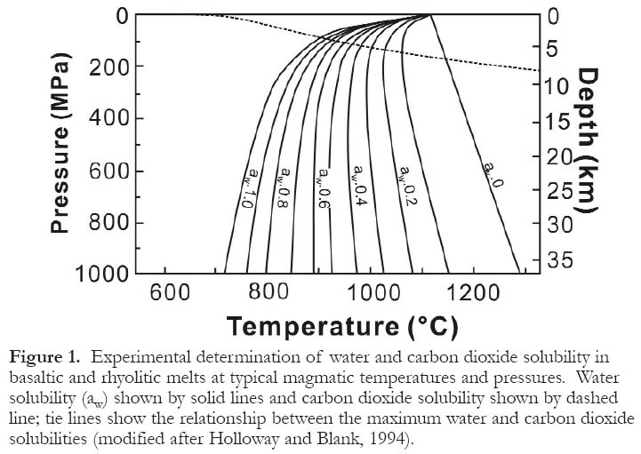
Display large image of Figure 1
4 The solubility of water in silicate melts is known for many magma types; this can be approximated by CS = k.P0.5, where CS is the saturated concentration, k is the solubility constant, and P is the pressure. Water dissolved in silicate melts occurs as hydroxyl groups (HO-) and as molecular water (H2O; Stolper, 1982, 1989). Their relative proportions vary systematically with total water content; in silicate melts that have low water contents, virtually all water occurs as hydroxyl groups and the proportion of molecular water increases as the water content increases (Wallace and Anderson, 2000). The activity of water in silicate melts varies as a function of P-T conditions and composition. In general, as the pressure and temperature of the melt decrease, the activity of water increases (Fig. 1). The solubility is greater in silica-rich melts (rhyolite) than in silica-poor melts (basalts) at typical melt temperatures and pressures above 50 MPa (Holloway and Blank, 1994; Fig.2).
5 The solubility of carbon dioxide in silicate melts has a similar relationship to that of water but is an order of magnitude smaller (Fig. 2). The lowered solubility of carbon dioxide in silicate melts is a function of melt structure and carbon dioxide availability in the crust or mantle where the melt is generated. Like water, carbon dioxide dissolves in silicate melts in two separate species, carbonate (CO32-) and carbon dioxide molecules (CO2). Unlike water, carbon dioxide speciation is controlled by the bulk composition of the silicate melt. Molecular carbon dioxide is more soluble in silica-rich melts (Fogel and Rutherford, 1990; Blank et al., 1993) than in silica-poor melts where carbonate is the dominant species present (Fine and Stolper, 1986).
6 Chlorine is another important volatile constituent in silicate melts, in that it affects the solubility of other volatile species. The solubility of chlorine is complex because a silicate melt can be saturated with an immiscible alkali chloride (molten salt; Koster van Groos and Wyllie, 1969). In the presence of water, the alkali chloride melt will also contain dissolved water. The solubility of chlorine in silicate melts is strongly dependant on silicate melt composition, and the solubility increases with increasing (Na + K)/Al values (Kotlova et al., 1960; Ryabchikov, 1963). Chlorine solubility varies with temperature, pressure, dissolved water content, and silicate melt composition (Kilinic and Burnham, 1972; Webster and Holloway, 1988; Shinohara et al., 1989; Malinin et al., 1989; Kravchik et al., 1998), but it generally is an order of magnitude less than carbon dioxide. This solubility is intermediate between water and carbon dioxide in silicate melts that are saturated in the volatile phase; maximum chlorine solubilities range from several ppm to ~ 2 wt. % (Carroll and Webster, 1994). It is important to note that chlorine will strongly partition into the exsolved volatile phase of silicate magmas; experimental studies indicate that the concentration, by mass, of chlorine in the vapour phase can be 5 to 20 times greater than the mass partitioned into the melt (Roedder, 1984). The formation of a saline-rich exsolved phase plays an important role in the formation of hydrothermal ore deposits and also plays an important role in the phase equilibria of water in such systems.
Figure 2. P-T projection of phase relations in the system NaAlSi3O8-H2O. The lines show the solubilities of H2O and CO2 as a function of pressure in this system (modified after Burnham, 1979).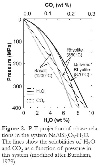
BUBBLE GROWTH AND NUCLEATION
7 The steady state crystallization of anhydrous phases in a magma chamber causes the remaining melt fractionation to become saturated or even supersaturated in volatiles leading to an increase in the volatile pressure. If the volatile pressure exceeds the confining pressure of the magma, then vesiculation (bubble nucleation and growth) can occur and the volatile phase is exsolved from the magma. The confining pressure may be atmospheric, hydrostatic, lithospheric or a combination of two of them, depending on the eruptive setting. Supersaturation of the volatile phase may occur via rapid crystallization of anhydrous phases in the melt or via rapid decompression of the magma chamber, which increases the liquidus and solidus of a particular melt, and decreases the maximum volatile solubility.
8 The presence of bubbles in the magma is not sufficient to cause an explosive eruption in and of itself, but plays a critical role in magmatic fragmentation where reservoirs build up magmatic gases. There are two end member mechanisms for bubble nucleation: homogeneous and heterogeneous. The former requires spontaneous nucleation of the volatile phase in a supersaturated crystal-free melt, whereas the later requires a nucleation site in a saturated melt.
9 Classical homogenous nucleation theory states that a bubble must reach a critical size radius (RCRIT) above which nuclei are stable and additional bubble growth can occur (Zettlemoyer, 1969). The critical bubble size occurs where the energy decrease, resulting from the creation of the volatile phase, more than offsets the energy required to maintain the volatile-melt interface (Fig. 3a). Homogeneous nucleation of bubbles requires extremely high supersaturation because there is a kinetic barrier to nucleation; therefore, the magma must rise in the conduit above the volatile saturation level before bubbles can form (Fig. 3b), or the chamber must decompress. In silicic melts where decompression is the saturation mechanism, homogeneous bubble nucleation requires rapid decompression, i.e., greater than 90-150 MPa, which leads to extreme water supersaturation and disequilibrium degassing (Mangan et al., 2004). In these magmas, the higher the bubble content, the faster is the decompression rate (Mourtada-Bonnefoi and Laporte, 2004). In highly viscous melts, the decompression rate may be too slow for bubble growth to maintain melt-bubble equilibrium, causing the melt to become extremely supersaturated in the volatile phase (Gardener et al., 1999). Whatever the mechanism, the delay in bubble nucleation causes supersaturation of volatiles in the melt phase and results in catastrophic nucleation, concentrating the energy from expansion into a very short time interval, which leads to highly explosive eruptions.
10 There is no kinetic barrier to heterogeneous nucleation of bubbles; therefore, the exsolution surface (level in the chamber or conduit) is synonymous with the saturation surface because volatiles exsolve during magma ascent (Fig. 3c). Heterogeneous nucleation models assume equilibrium degassing during magma ascent; heterogeneous nucleation may occur on growing crystals (Hurwitz and Navon, 1994). Published experimental data show that heterogeneous bubble nucleation is triggered by 0.001-1 MPa/s decompression with pressure changes less than 5 to 20 MPa in water-saturated rhyolite and leads to equilibrium degassing (Mangan et al., 2004; Mourtada-Bonnefoi and Laporte, 2004).
11 Once nucleation occurs, bubbles continue to grow in the melt as the magma approaches fragmentation. This growth is controlled by the diffusion of volatiles toward the bubble-melt interface, and viscous resistance to bubble expansion by the melt (Sparks, 1978; Hurwitz and Navon, 1994). At constant pressure, bubble growth occurs in two steps: exponential (viscosity-limited) growth and parabolic (diffusion-limited) growth. Bubble growth is initially exponential, when volatile diffusion is rapid and the bubble radius increases at a rate limited by the melt viscosity (Navon and Lakhovsky, 1998; Gilbert and Sparks, 1998). Bubble growth becomes parabolic when the growth rate is limited by volatile diffusion because the equilibrium saturation pressure in the bubble cannot be maintained by the flux of water through the bubble-melt interface (Gilbert and Sparks, 1998; Navon and Lakhovsky, 1998).
12 Over long intervals, bubble growth will be influenced by the proximity of neighbouring bubbles and may diverge from the parabolic growth model. Bubble growth is also controlled by the rate of decompression relative to rates of exponential- and parabolic-limited growth (Cashman et al., 2000).
13 Rapid decompression causes bubble growth to be out of equilibrium with the melt leading to supersaturation conditions that are important in magmatic fragmentation and may cause large decreases in melt viscosity. Experimental studies show that at high water contents a bubble maintains equilibrium with the melt, but at low water contents growth is inhibited by high-melt viscosities (Sparks, 1978; Sparks et al., 1994; Proussevitch and Sahagian, 1998; Proussevitch et al., 1993, 1996; Hurwitz and Navon, 1994; Toramaru, 1995; Jaupart, 1996; Lyakhovsky et al., 1996).
14 It is unlikely that in a natural system a homogeneous end member type of bubble nucleation will occur alone, because nucleation mechanisms are a function of magma crystallinity and decompression rates (Mangan et al., 2004). The formation of crystal phases in the magma chamber during fractionation will favour heterogeneous bubble nucleation. Where the crystal contents are low, isolated homogeneously nucleated bubbles will form because heterogeneously nucleated bubbles cannot keep pace with magmatic decompression. The magma crystallinity and decompression rate also control whether the eruptive degassing occurs early (deep) under quasi-equilibrium conditions or late (shallow) at extreme supersaturation (Mangan et al., 2004).
Figure 3. Bubble Nucleation. (a) Total energy vs. bubble radius; bubbles must reach a critical radius size for bubble growth to occur. (b) Schematic diagram of homogeneous nucleation in the conduit, note that the exsolution surface (level) is significantly higher than the saturation surface indicating that melts must be super-saturated in volatiles before nucleation and bubble growth can occur. (c) Schematic diagram of heterogeneous nucleation in the conduit, note that the exsolution and saturation surfaces occur at the same height in the conduit (modified after Cashman et al., 2000).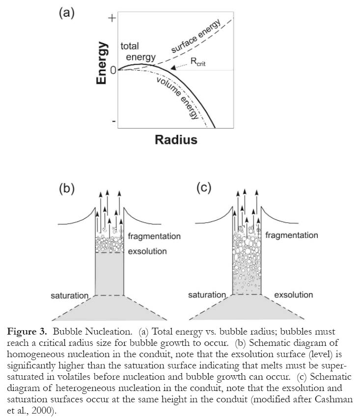
FRAGMENTATION OF MAGMA
15 Fragmentation of magma has been covered by many authors (Alidibirov and Panov, 1994; Klug and Cashman, 1994; Gardner et al., 1996; Alidibirov and Dingwell, 1999; Papale, 1999; Martel etal., 2001; Gonnermann and Manga, 2003), but a general treatment can be found in Cashman et al. (2000). Fragmentation of magma, sensu stricto, is the transformation of magma from liquid foam with dispersed gas bubbles to gas with dispersed liquid drops or isolated particles (Cashman et al., 2000). Magma disruption is caused by overpressures within the bubbles at the fragmentation surface (Sparks, 1978). The fragmentation surface occurs where gas occupies 68 to 93% of the available volume, based on the experimental results of Papale (1999), with higher values corresponding to mafic melts and lower values to silicic ones. Fragmentation of magma is accompanied by a large density decrease, reflecting the change from magmatic to hydrostatic volatile pressures, thereby producing a large volume increase. It is the expansion of the volatile phase following exsolution and magmatic fragmentation which produces the kinetic energy required to accelerate the magma-volatile mixture to the surface producing an explosive eruption.
16 There are two models to describe magmatic fragmentation: rapid acceleration and rapid decompression. Fragmentation resulting from rapid acceleration of magma is caused by the expansion of the volatile phase, thereby producing magmatic foam. Once the bubble walls become sufficiently thin, the magmatic foam becomes unstable and begins to break apart. The fragmentation of the magmatic foam is violent and causes the bubble clasts to colide against the conduit wall and with each other resulting in finely dispersed fragments (Cashman et al., 2000). Fragmentation resulting from rapid decompression of the magma causes a bubble row at the edge of the foam to fail by rupture or solid fracture when low ambient pressures are reached. Rupturing of the initial row causes lower bubble rows to fragment in the same fashion leading to a sequential inward progression of the fragmentation process. This type of fragmentation best explains volcanic blasts where the depressurization front moves downward rapidly (several tens of metres per second; Cashman et al., 2000).
THE GENERATION OF PYROCLASTIC MAGMATISM AND SUBAQUEOUS PYROCLASTIC FLOWS
17 Pyroclastic eruptive systems consist of (a) a gas/pyroclast mixture extending from the level of the disintegrating magma column to the point of extrusion and (b) a visible eruption column (Fisher and Schmincke, 1984). Pyroclasts are produced by the explosive fragmentation of magma; this fragmentation occurs in the magma conduit or at high levels in the magma chamber (Fig.4). Pyroclasts are deposited by fallout, flow and surge mechanisms. Each deposition mechanism may occur in a subaerial or submarine setting, although in the latter it is likely that pyroclasts are reworked to some degree and thus are classified as volcaniclastic deposits.
18 Pyroclastic flows may be formed either subaerially or subaqueously and are generated by dome collapse, eruption column collapse, or a boiling over eruption (Cas and Wright, 1987); water acts as an efficient sorting medium for pyroclastic eruptions. Deposits resulting from eruption column collapse in a subaqueous environment are generally depleted in fine pyroclastic material, reflecting elutriation of this material via hydraulic sorting during flow movement (Fiske and Matsuda, 1964; Stix, 1991; McPhie et al., 1993). Pyroclastic flow deposits from boiling-over eruptions are commonly less depleted in fine material, reflecting the reduced interaction with water during flow movement (McPhie et al., 1993; Gibson et al., 1999). A full treatment of the deposits generated by pyroclastic eruptions in the deep subaqueous environment is beyond the scope of this paper.
19 An important consideration in the generation of pyroclastic flows and their deposits in the deep marine environment is heat retention. Dr. R.S. Fiske (personal communication, 2005) has been looking for hard evidence of heat retention in submarine pyroclastic deposits. In a number of Japan Agency for Marine-Earth Science and Technology (JAMSTEC) cruises, he has examined many dredged hauls and viewed hundreds of hours of dive tapes, but has never observed any evidence of welding or sintering. Since water has a
20 very high heat capacity and thermal conductivity compared to air, magma interacting with water causes quench granulation if the encounter is sufficiently energetic (Thorarinsson, 1967; Moore et al., 1973; Kokelaar, 1986) or if melt domains are very small (Carlise, 1963). For pyroclastic eruptions of magmatic or phreatomagmatic origin, the high heat capacity and thermal conductivity of water leads to rapid heat transfer and potentially to another phase of fragmentation (Gudmundsson, 2003). More importantly, pyroclastic eruptions into a water column cause the rapid cooling of pyroclasts because of the thermal properties of water, explaining the lack of evidence for heat retention in deep subaqueous pyroclastic flows. However, in rare cases the pressure of the overlying water column may be high enough to produce tufflava (tuff-like/lava-like rocks) that contain evidence of heat retention (cf., Downey, 2005).
Figure 4. Models for subaqueously deposited pyroclastic flows. (a) Pyroclastic flows of subaerial origin. (b) Pyroclastic flows of subaqueous origin at shallow depths (up to 1 km). (c) Pyroclastic flows of subaqueous origin in deep water (4 km) (modified after Schneider, 2000).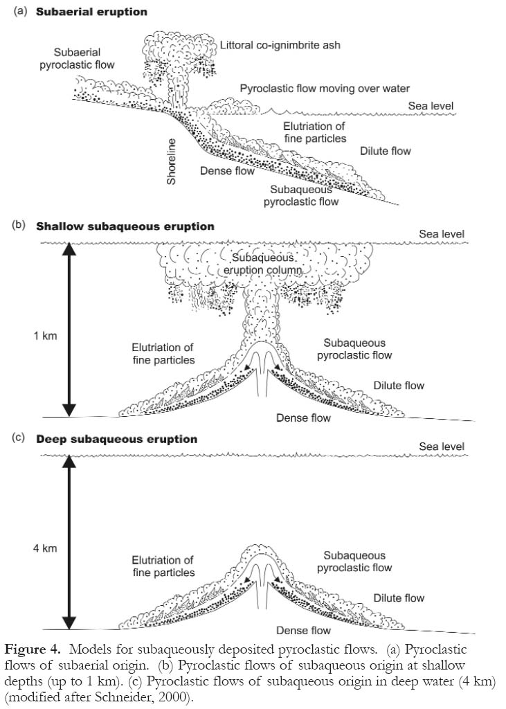
BURNHAM MODEL
21 Burnham (1983) proposed that highly explosive eruptions can occur from shallow crustal magma chambers at water depths as great as 3.5 km. During these eruptions, the energy released is a result of rapid crystallization in the chamber, which exsolves water and other volatiles, and it is high enough to drive a major explosive eruption. This hypothesis is illustrated by a series of mathematical equations that Burnham (1983) used to model the energy released from the exsolution of water in rhyolitic magma. In silicic melts that contain more than a few tenths of 1 wt. % H2O, the rate of exsolution of water (vesiculation) is sufficiently rapid to contribute to the explosivity of pyroclastic eruptions.
22 The principal factor controlling the exsolution is the diffusivity (D) of water in a melt; diffusivity is inversely dependant on viscosity (η) and viscosity is inversely dependant on the water content of the melt (Burnham, 1967). This relationship is best modelled by the Eyring relation (Rubie et al., 1993):


23 In a silicic magma chamber, with an initial water content greater than 0.5 wt. %, cooling inward from the margins results in the crystallization of anhydrous minerals leading to saturation of water in the melt phase (Burnham, 1983). Further crystallization will lead to exsolution of water by resurgent (second) boiling (H2O-saturated melt → melt + H2O vapour). The mechanical energy released during crystallization of anhydrous phases can be calculated for various pressures from the equation:

24 The mechanical energy released by the exsolution of additional water, as a result of decompression related to the failure of wall rocks, is adequate to produce pyroclastic eruptions at significant depth. This can be derived from equation 3, by dropping the last term that represents the change in volume upon crystallization (-∆Vm ) from the melt during resurgent boiling. The equation then becomes:

25 Decompression related to wall rock failure results in the expansion of already exsolved water bubbles and the exsolution of additional water. The energy associated with bubble expansion can be approximated by the ideal gas law, in the form:


CAS MODEL
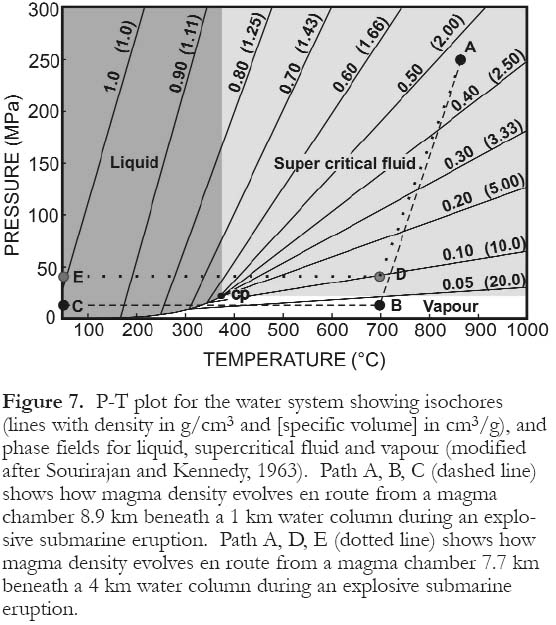
26 Cas (1992) discussed the constraints on eruption styles including the maximum depth that explosive pyroclastic eruptions can occur. He emphasized the role that the ambient conditions play in the inhibition of deep submarine pyroclastic eruptions, i.e., the overlying hydrostatic pressure is greater than the pressure of the magmatic volatiles. Thus the explosive expansion (two-phase liquid-vapour field) of superheated seawater in contact with erupting magma is inhibited. This conclusion is reached by his examination of the water liquid-vapour curve, mainly the significance of the critical point of water. The critical point of water is the point at which there is no distinction between the liquid and vapour phases (supercritical fluid); for pure water it is 21.6 MPa (2.16 km water depth) and for seawater it is 31.5 MPa (3.15 km water depth; Sourirajan and Kennedy, 1962). The critical point of carbon dioxide is 75 bars equivalent to 750 m water depth, significantly less than water. Cas (1992) concludes that explosive eruptions must occur at a seawater depth much shallower than the critical point, i.e., between 0.5 to 1.0 km for most magmas, because water is exsolved in the liquid state (Moore, 1965) and the fluid pressure of the exsolving volatile phase is not high enough to expand explosively against the ambient hydrostatic seawater pressure. However, what he failed to consider is that magmatic water exsolved at P-T conditions above the critical point will exist as a supercritical fluid (Fig. 7), causing orthomagmatic volatile expansion and melt fragmentation. Supercritical fluids have a significant volume change upon crossing into the liquid field (Fig.7).
MODELLING USING CONFLOW
27 To evaluate the conditions necessary for a submarine pyroclastic eruption to occur at depths of greater than 1 km and even those greater than 3.5 km (beyond the critical point of seawater), we applied the 1-D numerical model CONFLOW (Mastin and Ghiorso, 2000). This program models the steady-state, non-separated flow of magma-H2O mixtures through a cylindrical, vertical eruptive conduit of constant cross-sectional area where no heat is transferred across the conduit walls during eruption under equilibrium conditions. Details of the CONFLOW model and equations used can be found in Appendix 1.
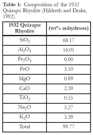
28 For our modelling, the melt composition that was used is the 1932 Quizapu Rhyolite (Hildreth and Drake, 1992), specifically sample Q-4 shown in Table 1. The solubility curve for this melt is shown in Figure 2. A fixed conduit diameter of 10 m was used with varying conduit lengths in order to compensate for the depth of the overlying water column. The initial temperature of the magma is taken to be 870 ºC, and models were generated with a crystallinity of 0 vol. % orthoclase to mimic homogenous nucleation and 15.7 vol. % orthoclase to mimic heterogeneous nucleation. To constrain the number of models generated using CONFLOW, we have chosen to present a model using Burnham's criteria for a shallow level magma chamber (1.4 km below sea floor) erupted in 3.5 km water depth. Two additional models that constrain eruptions in relatively shallow water (~ 1 km) and in the deep ocean (~ 4 km) are also presented, which correspond to magma chambers at 8.9 km and 7.7 km below the sea floor, respectively. To mimic nucleation in silicic magma chambers, we have chosen to increase the initial water content of the magma mixture from undersaturated to supersaturated at 5, 10, 12, 15, and 17 wt. %, respectively. It is important to note that the velocities of the magma-volatile mixtures are for pressurized conditions and do not assume injection into air (i.e., calculated for the maximum theoretical velocity).
Table 1: Composition of the 1932 Quizapu Rhyolite (Hildreth and Drake, 1992).
Display large image of Table 1
Display large image of Figure 6
Display large image of Figure 7
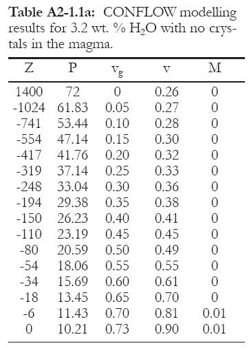
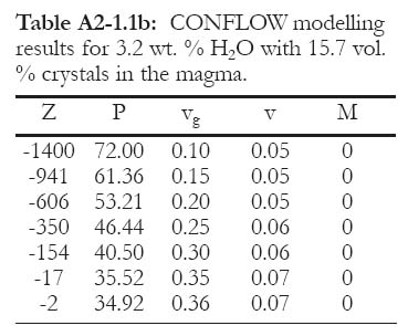
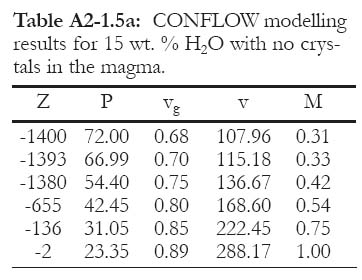
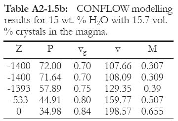
29 The results of modelling using the Burnham criteria for a shallow level magma chamber, i.e. 1.4 km beneath a 3.5 km water column, are shown in Figure 8 and can be found in Appendix 2. The total pressure at this depth including the water column is 72 MPa. The CONFLOW model predicts that magmatic fragmentation will occur at 5, 10, 12, and 15 wt. % H2O for a magma that has no crystals and at 12 and 15 wt. % H2O for a magma with 15.7 vol. % crystals. The fragmentation depth for the aphyric magma occurs near the base of the conduit for water contents of 10% or more. The exit conditions show that the velocity of the volatile-magma mixture ranges from insignificant to 198.57 m/s, the lower exit velocities representing low water contents. The Mach number at the exit conditions predicts that the pyroclastic material will exit the vent at supersonic speeds for 10, 12, and 15 wt. % H2O in magma with no crystals and at subsonic speeds for all water contents in magma with 15.7 vol. % crystals.
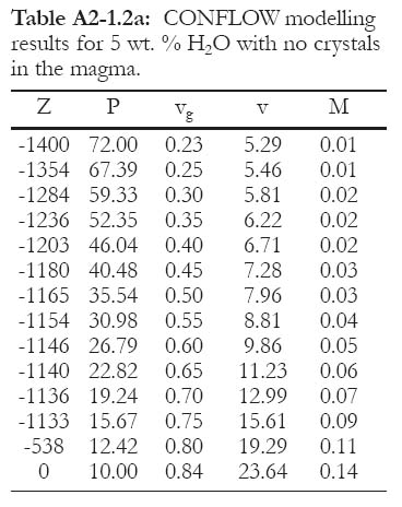
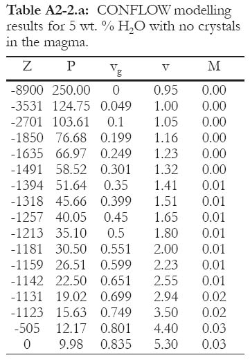
30 The modelling results for an intermediate level magma chamber in shallow water, i.e., 8.9 km beneath a 1 km water column, are shown in Figure 9 (and can be found in Appendix 2). The total pressure at this depth including the water column is 250 MPa. The CONFLOW model predicts that magmatic fragmentation will occur for all water contents tested, from just below saturated (5 wt. %) through extremely supersaturated (15 wt. %) conditions. The fragmentation depth varies with crystal and water content, the higher the water content the deeper the fragmentation level, e.g., for 5 wt. % H2O, the fragmentation level occurs at 1.1 km (0 vol. % crystals) and 1.3 km (15.7 vol. % crystals), whereas under extremely supersaturated conditions, 12 wt. % H2O, the fragmentation level is at 4.6 km (0 vol. % crystals) and 5.9 km (15.7 vol. % crystals). The exit conditions show that the velocity of the volatile-magma mixture ranges from 0.95 m/s to 294.27 m/s, the lower exit velocities representing lower crystal and water contents. The Mach number for magma with no crystals (Fig. 9a) predicts that the pyroclastic material will exit the vent at subsonic speeds for 5, 10, and 12 wt. % H2O and at supersonic speeds for 15 and 17 wt. % H2O. The Mach number for magma with 15.7 vol. % crystals (Fig. 9b) predicts that the pyroclastic material will exit the vent at subsonic speeds for 5, 10, and 12 wt. % H2O and supersonically for 15 and 17 wt. % H2O.
Figure 8. CONFLOW modelling results for an explosive eruption from a magma chamber that is 1.4 km beneath a 3.5 km water column. The upper part of the diagram (a) represents an aphyric (without crystals) rhyolitic magma and the lower part (b) is the same magma with 15.7 vol. % crystals. Five different water saturation levels are shown. See Appendix 2 for details.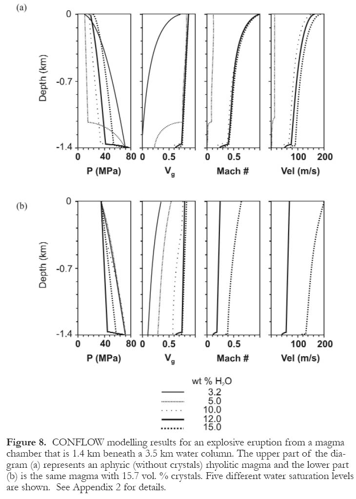
Display large image of Figure 8
31 The modelling results for an intermediate level magma chamber in deep water, i.e., 7.7 km beneath a 4 km water column, are shown in Figure 10 (and can be found in Appendix 2). The total pressure at this depth including the water column is 250 MPa. The CONFLOW model predicts that magmatic fragmentation will only occur approximately 2 to 4 km below the sea floor in extremely oversaturated conditions, i.e., greater than 12 wt. %, consistent with the observations of Mangan et al. (2004). The exit conditions show that the velocity of the volatile-magma mixture varies from 0.88 m/s in undersaturated melt to 61.96 m/s in supersaturated melt. The Mach number predicts that the pyroclastic material will exit the vent at subsonic speed for all water contents modelled regardless of the crystal content.
DISCUSSION
32 There may be a complementary relationship between the role that magmatic fluids play in generating explosive eruptions and in the genesis of large VMS deposits (Lentz et al., 1999). Sea floor exhalative, volcanic massive sulfide deposits are commonly intimately associated with felsic volcanic rocks in both the footwall and (or) hangingwall sequences (Gibson et al., 1999). The massive sulfide bodies themselves suggest deep-water conditions for deposition as they lack evidence of extensive boiling of the exhalative fluids (Lentz et al., 1999). Many of the associated felsic rocks have been interpreted as mass-flow deposits from shallow water instead of primary, deep-water, pyroclastic deposits because of Cas' (1992) interpretation of the significance of the water liquid-vapour curve to pyroclastic eruptions. However, evidence from the modern sea floor (Wright et al., 1998; Worthington et al., 1999; Bloomer et al., 2001; Fiske et al., 2001; Wright et al., 2003; Yuasa and Kano, 2003) supersedes Cas' interpretation. In addition, fluid inclusion evidence from the Bald Mountain Cu-Zn deposit (Maine) indicates eruption at a depth of 1.45 km (Foley, 2003) consistent with facies analysis of the volcanic sequence (Busby et al., 2003). At the Brunswick No. 6 and No. 12 Pb-Zn deposits (New Brunswick), the presence of peperites in association with pyroclastic rocks and tufflavas indicates the in situ emplacement of pyroclastic rocks (cf., Downey, 2005). This, and the presence of mud-stone and laminated fine-grained tuff in the footwall and hanging wall sequences, suggests a deep-water depositional environment.
33 Prior to Burnham's (1983) work there had been no viable mechanism identified to generate the enormous amounts of energy required to initiate explosive pyroclastic eruptions under water. The commonly held view (cf., Williams and McBirney, 1979) was that the mechanical energy produced during an explosive eruption was generated by the expansion of pre-existing bubbles in the melt (Sparks, 1978) as a result of a series of small decompressions (0.001-0.01 MPa). Burnham's (1983) model was later used to explain the mechanics behind the submarine pyroclastic flows as described by Fiske and Matsuma (1964). The commonly held view today is that explosive eruptions are generated by the homogeneous nucleation of bubbles in a supersaturated magma (see Mangan et al., 2004).
Figure 9. CONFLOW modelling results for an explosive eruption from a magma chamber that is 8.9 km beneath a 1 km water column. The upper part of the diagram (a) represents an aphyric (without crystals) rhyolitic magma and the lower part (b) is the same magma with 15.7 vol. % crystals. Five different water saturation levels are shown. See Appendix 2 for details.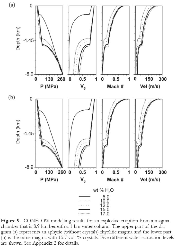
Display large image of Figure 9
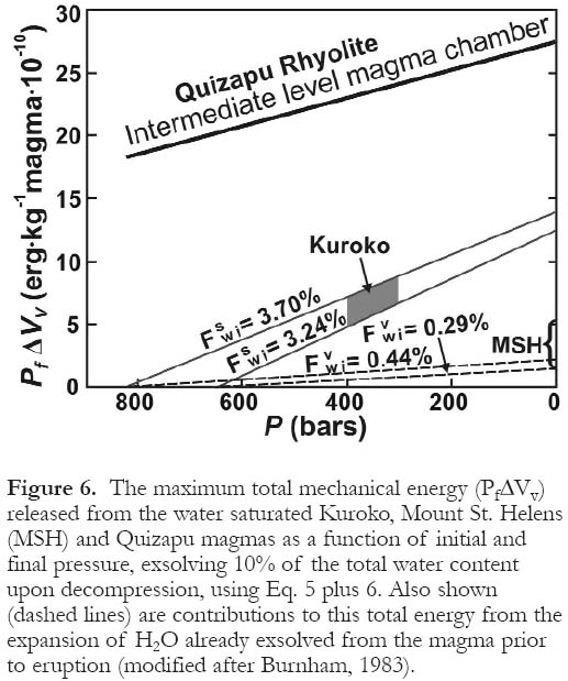
34 Burnham (1983) modelled the energy released by the T3 and T4 Hokuroko rhyolitic tuffs (Ohmoto, 1978). The tuffs were interpreted to have been erupted at a water depth of 3500 m (Guber and Merrill, 1983) from a shallow magma chamber (750 to 1400m) with crystallinity of 20 vol. % and from a volatile saturated magma. The P∆V work of expansion releases between 1.1 × 10¹⁰ergs· kg -1(Eq. 3) and 1.5 × 10¹⁰ergs· kg -1(Eq. 5) from the magma for the first phase of exsolution, and 3.5 × 10¹⁰ergs· kg -1(Eq. 4) and 7.8 × 10¹⁰ergs· kg -1(Eq. 6) from the magma following wall rock failure (Fig. 6). The mechanical energy produced using the Burnham model is greater than that of the Mount St. Helens blast (Eichelberger and Hayes, 1982); hence adequate mechanical energy was available to produce deep submarine explosive eruptions in the Hokuroko district. Interestingly, more energy is released from an intermediate level magma chamber (250 MPa), upon the exsolution of water and subsequent wall rock failure, than from either the Kuroko or Mount St. Helens eruptions (Fig. 6). The increase in mechanical energy (P∆V work of expansion) from a deeper level magma chamber can be explained by the increase in the solubility of volatiles as pressure increases. This is an important contributor to explosive volcanism, if not the dominant one, and is especially true in a deep subaqueous environment where the pressure of the overlying water column is significant.
35 Cas (1992) disagreed with Burnham's hypothesis, because Burnham (1983) did not attempt to demonstrate that the pressure exerted by the volatile phase in vesicles would be significantly higher than the ambient seawater pressure. However, this is irrelevent because fragmentation occurs from orthomagmatic volatile expansion in the conduit prior to eruption if the pressure is above the critical point of seawater, i.e., before the magma reaches the seafloor. This does not apply to phreatic eruptions (bulk-interaction steam explosivity and contact-surface steam explosivity), as shown by Wohletz (2003), nor is it applicable to magmatic pyroclastic eruptions.
36 Rapid decompression associated with homogenous nucleation leads to explosive pyroclastic fragmentation. An average rhyolitic magma undersaturated in water remains under lithostatic pressure until saturation is reached. The magma begins to crystallize anhydrous minerals thereby increasing the dissolved water content in the melt. When the activity of water is sufficiently high (i.e., aH2O ≥ 1), the vapour phase exsolves as a supercritical fluid having a low density (large volume) and causing pressure to build up within the magma chamber. However, in some cases the volatiles may become trapped in the melt structure, because of the high shear viscosity of the magma, leading to oversaturation. As crystallization proceeds, the magma and volatile system expands (increasing ∆V) causing tensional fracturing of the wall rocks.
37 Once tensional fracturing of the wall rocks occurs, the system becomes essentially self-sustaining because the exsolved portion of the volatile phase rapidly increases. This is caused by the rapid decompression of the system, which causes the solidus to shift to a higher temperature upon decompression (Fig. 11). This causes the magma to pressure quench and crystallize anhydrous minerals, which leads to extreme supersaturation in the residual melt. The exsolution of the excess volatile phase continues as the magma chamber decompresses toward lithostatic pressure. The extreme degree of supersaturation produced upon decompression drives the entire system to sustain a pyroclastic eruption until the pressure in the magma chamber is returned from supralithostatic to sublithostatic.
Figure 10. CONFLOW modelling results for an explosive eruption from a magma chamber that is 7.7 km beneath a 4 km water column. The upper part of the diagram (a) represents an aphyric (without crystals) rhyolitic magma and the lower part (b) is the same magma with 15.7 vol. % crystals. Five different water saturation levels are shown. See Appendix 2 for details.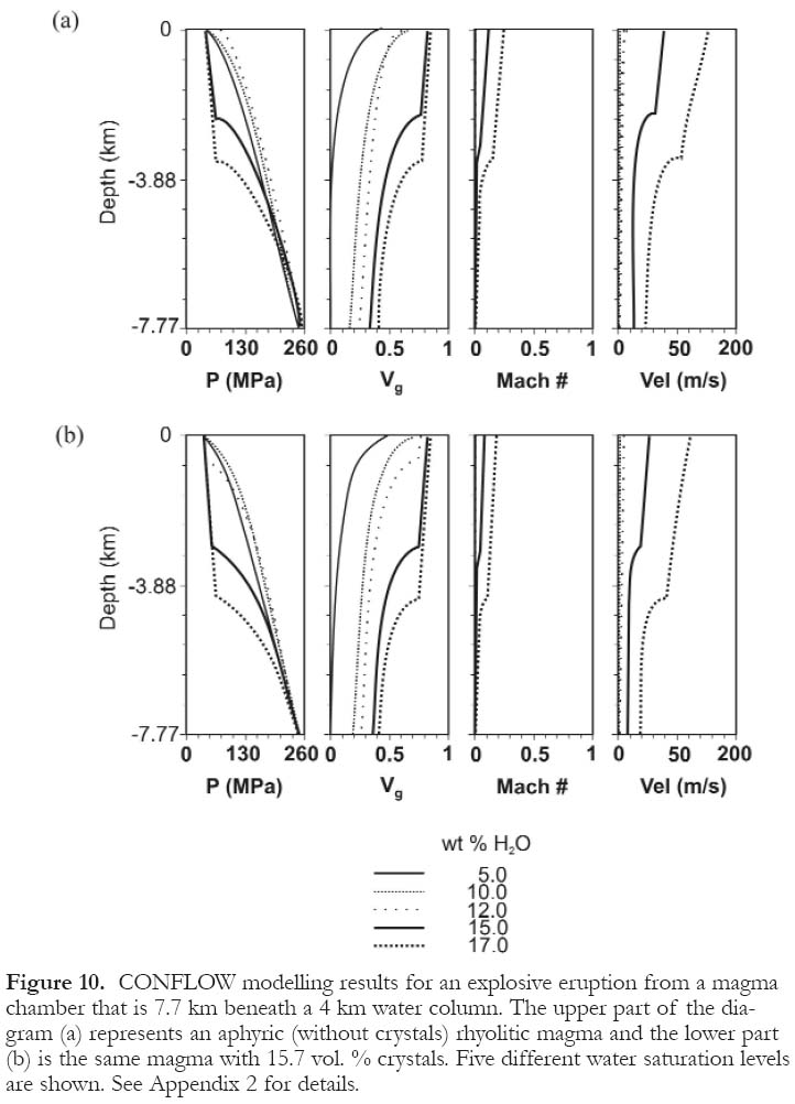
Display large image of Figure 10
38 Volatile phase expansion, specifically the increase in volume (cm3) associated with low density fluids (Fig. 7) in the supercritical field, plays a key role in deep submarine explosive eruptions. Volatiles may not expand instantaneously (as they do not cross the subcritical liquid-vapour phase boundary), but the volumetric expansion in the gas-pyroclast mixture as it moves through the crust and into the water column is enormous because the system goes from a relatively dense supercritical fluid to a very low density supercritical fluid or vapour phase.
39 When the volume fraction of volatiles in the magmatic conduit is between 68 and 83 vol. %, magmatic fragmentation occurs. The gas-pyroclast mixture continues to move upward, becoming progressively less dense as pressure decreases, and therefore, volumetrically larger. The volatile phase expansion of the volatile-magma mixture rises from the fragmentation level rapidly (10s to 100s of m/s) due to a pressure decrease from 250 MPa to 10 MPa (~1 km water depth). A volatile-magma mixture at the fragmentation surface with a temperature of 850 ºC has a density of 0.47 g/cm3, and a final erupted volatile-magma mixture with a temperature of 700 ºC has a density of 0.025 g/cm3(Fig. 7), a 1880 times volume expansion. The volume expansion at the base of the water column is approximately 4100 times, because the density of the seawater at 4 ºC is 1.026 g/cm3. If we consider the volatile phase expansion of the volatile-magma mixture with similar parameters, but erupting in a 4 km water column (~ 40 MPa), the density would change from 0.47 g/cm3 to 0.10 g/cm3(Fig. 7), a 470 times volume expansion. The volume expansion at the base of the water column would be approximately 1000 times.
40 Combining the use of volatile phase expansion and modelling using CONFLOW, the plausibility of deep submarine pyroclastic volcanism becomes apparent. The results show that fragmentation will occur in rhyolitic magma whether or not crystals are present. Under a 1 km (10 MPa) water column with the top of the magma chamber at 8.9 km, fragmentation occurs for all modelled water and crystal contents (Fig. 9). The exit speeds vary and are dependant on the amount of water present in the melt, with supersaturated (15 and 17 wt. % H2O) volatile-magma mixtures leaving the vent at supersonic velocities. Under the same conditions where eruptions are occurring in a 4 km (40 MPa) water column, fragmentation is initiated in those melts with supersaturation ~ 2 times the maximum solubility of the melt. The exit velocities are much lower than in the shallow water model and the volatile-magma mixtures exit the vent at subsonic conditions (Fig.10).
Figure 11. Temperature-XH2O diagrams for synthetic granite showing the stable phase assemblages (black lines) and volume percent melt (grey lines). Paths A, B, and C (dotted line) is the crystallization path of a melt undergoing crystallization leading to the tensional fracturing of wall rocks and subsequent quench crystallization driving explosive eruptions. (a) At a confining pressure of 800 MPa. (b) At a confining pressure of 200 MPa (modified after Whitney, 1989).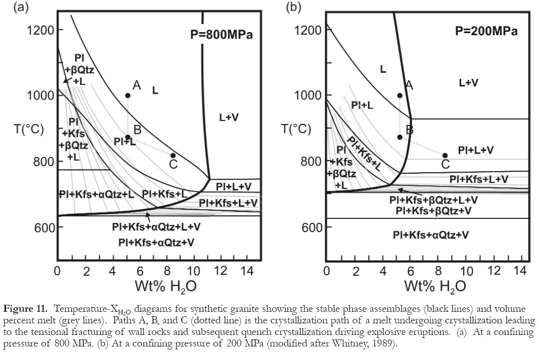
Display large image of Figure 11
41 Alternatively, we can use the conditions proposed by Burnham (1983) to show that even shallow magma chambers, when supersaturated in the volatile phase, are capable of initiating pyroclastic eruptions even at significant water depths. Under a 3.5 km water column with the top of the magma chamber at 1.4 km (72 MPa), supersaturation of ~3 to 4 times is required to initiate fragmentation (Fig. 8). The maximum solubility of the 1932 Quizapu Rhyolite (Hildreth and Drake, 1992) is 3.2 wt. % H2O at 72 MPa. If the magma becomes supersaturated in the volatile phase, it is capable of fragmenting in the conduit near the top of the magma chamber (~12 wt. % H2O) and exiting the vent at high - but not supersonic - velocities (Fig. 8).
42 In a shallow submarine environment, sonic to supersonic eruptions should produce eruption columns similar to those in the subaerial environment (Fig. 4b). However, the column height and degree of mixing would be suppressed because the viscosity and density of air is much lower than water. In addition, the rate of column collapse would be more rapid, because water is a more efficient medium for cooling than air, and also because of its high heat capacity. Therefore, one would expect to see a modified depositional sequence, marked by well-sorted units as water is a more effective sorting medium than air.
43 In the deep-water environment, the eruption column dynamics will differ from the shallow environment (Fig. 4c). At exit velocities below sonic conditions one would predict a boiling over, directed pyroclastic eruption (Fig. 4c) as opposed to an eruption column with an ash-fall deposit followed by a pyroclastic flow sequence and subsequent ash-fall deposition. It is possible that extremely volatile-supersaturated, crystalline magma-volatile mixtures may be driven high into the conduit prior to fragmentation. Because the deep water will suppress the eruption column, we predict that it is possible to have a coarse crystalline pyroclastic unit. Evidence for this can be seen in pyroclastic deposits associated with the Brunswick volcanic massive sulfide deposits (Lentz et al., 1999), where thick units (10s m) of pyroclastic material with large quartz and feldspar phenoclasts (up 10 cm in length) are preserved. These units are primary pyroclastic, and have been interpreted as tufflavas (cf., Downey, 2005). A similar unit, of coarse-crystalline rock that is fines depleted, has been observed at Bald Mountain, Maine (Busby, 2005; Busby et al., 2003) and at the Rosebury deposit, Tasmania (Allen and Cas,1990).
44 The CONFLOW and volume expansion models presented in this paper only take the pure water system into consideration. Because many other volatiles are present in real volcanic systems, it is important to consider the effects of these volatiles on the critical point of water and in initiating deep submarine pyroclastic eruptions. Carbon dioxide, for example, is an important constituent in any magma; rhyolitic magmas typically can contain 25 to 1000 ppm dissolved CO2 (Lowenstern, 2001). Carbon dioxide behaves in a similar fashion to water as it exsolves from a melt, but it is volumetrically less significant than water because it has a higher density as temperature increases. The main factor controlling P∆V is the expansion of the dissolved volatiles; therefore, the energy released from a vesiculating magma containing dissolved carbon dioxide will be slightly less than that of a magma containing only dissolved water.
45 Another factor affecting the explosivity of an eruption is the salinity of the orthomagmatic fluid. The addtion of NaCl to the water system increases the P-T condition of the critical point (Fig. 12). If we assume that a typical magmatic fluid has a salinity of 10 wt. %, then the critical point would be at 45.6 MPa (Sourirajan and Kennedy, 1962), significantly greater than the critical point of seawater. As the critical point shifts, so do the isochores; therefore, the fluids that are exsolving off the magma will be volumetrically larger than in the pure water system, thereby increasing the explosivity of the eruption.
CONCLUSIONS
46 Explosive silicic eruptions are possible in the deep submarine environment, at volatile concentrations and magma chamber/conduit geometries that are reasonable for many volcanic-tectonic environments.
Figure 12. P-X diagram for the NaCl-H2O system showing isotherms for 600ºC -700ºC with coexisting compositions of gases and liquids, and the critical curve for increasing NaCl content (Sourirajan and Kennedy, 1962).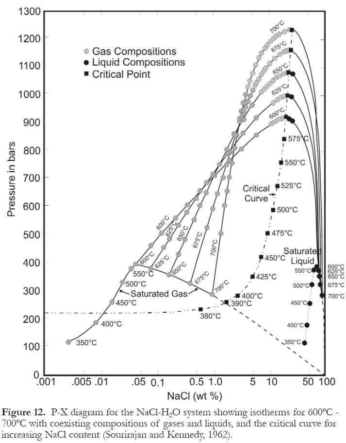
Display large image of Figure 12
47 Modelling of the Quizapu Rhyolite using CONFLOW shows that explosive silicic eruptions are capable of occurring in the deep submarine environment (i.e., at depths much greater than 1000 m) from a shallow (72 MPa) or intermediate level (250 MPa) magma chambers.
48 In very deep water environments, the character of the eruption column will change because the pressure of the overlying water column is significant and the magma-volatile mixtures do not exit the vent at Mach speeds.
49 Extreme supersaturation (2 to 4 times) is required to produce explosive eruptions at depths greater than the critical point of seawater.
APPENDIX 1
CONFLOW (Mastin and Ghiorso, 2000) models the steady-state, non-separated flow of magma-H2O mixtures through a cylindrical, vertical eruptive conduit of constant cross-section where no heat is transferred across the conduit walls during eruption under equilibrium conditions. The CONFLOW model is based on a series of equations of conservation of mass, momentum, and energy. This model has made several advances over previous conduit modelling programs because it incorporates: 1) a non-Arrhenian viscosity relation for hydrous melts; 2) a relation between bulk viscosity and volume fraction gas dependant on capillary number; 3) adiabatic temperature changes using established thermodynamic relations for melts and water vapour, respectively.
In the CONFLOW model, the flow of magma and exsolved H2O is homogeneous (i.e., there is no relative movement between the gas and the liquid as they ascend the conduit as it allows for the mixture to be treated as a single phase whose density, viscosity, and other properties are bulk values), and water exsolution maintains equilibrium in the conduit until the fragmentation point. CONFLOW solves the following equation for flow properties as a function of depth:


In CONFLOW, melt composition, conduit diameter and length, and the initial temperature and pressure at the base of the conduit are specified. The melt composition that was used is the 1932 Quizapu Rhyolite (Hildreth and Drake, 1992), specifically sample Q-4 shown in Table 1. A fixed conduit diameter of 10 m was used with varying conduit length to obtain constant crustal pressures to compensate for varying depths of the overlying water column. The depth to the base of the conduit was calculated using the following equation:

Implicit to the model is the assumption that the magma chamber feeding the conduit maintains constant pressure, and the volatile-magma mixture moves together with no heat loss or volatile loss to the surrounding wall rocks. From the initial input parameters, CONFLOW calculates the pressure gradient in a conduit of constant cross-sectional area (Equation A-1) and the enthalpy of the magma (Equation A-2). Once these variables are determined CONFLOW runs a step-wise series of iterations to extrapolate the pressure to the next higher elevation then re-evaluates the solution to equations A-1 and A-2. The magma is assumed to exit the vent at a Mach number ~1 (choke velocity), CONFLOW adjusts the initial velocity to meet this condition. The Mach number is defined as the velocity of the volatile-magma mixture divided by the mixture’s sonic velocity. The latter is defined as:

CONFLOW calculates the viscosity of the volatile-magma mixture at specified P-T conditions using the non-Arrhenian relations of Hess and Dingwell (1996):


The fragmentation depth is traditionally assumed to be the point where vg ≌ 0.75, the gas volume fraction where spherical bubbles reach closest packing (Sparks, 1978). However, the fragmentation criterion of Papale (1999) is likely a better approximation to calculate the point of fragmentation, which is equivalent to the depth where the extensional-strain rate within the conduit exceeds that which can be accommodated by viscous flow. Papale's criterion is mathematically expressed by:

APPENDIX 2
The following results summarize output from the CONFLOW modelling. Three sets of tables labelled A2-1, A2-2 and A2-3 are shown which have (a) and (b) parts. Each table presents the depth below the sea floor (z) in metres, the pressure (P) at this lithostatic depth in MPa, the volume fraction of gas present (v g), the velocity (v) of the rising gas-pyroclast mixture in metres per second, and the Mach number (M). In order to constrain the number of data points presented, we have chosen to only report data for changes of vg = 0.05, as well as the initial and final conditions.
The first set of tables (A2-1) models a shallow magma chamber at 72 MPa, which corresponds to a lithostatic depth of 1.4 km underneath a 3.5 km water column. The results for an aphyric magma (a) and crystal rich magma (b) with five different water contents (3.2, 5, 10, 12, and 15 wt. %) are shown.
Table A2-1.1a: CONFLOW modelling results for 3.2 wt. % H2O with no crystals in the magma.
Display large image of Table A2-1.1a
Table A2-1.1b: CONFLOW modelling results for 3.2 wt. % H2O with 15.7 vol. % crystals in the magma.
Display large image of Table A2-1.1b
Table A2-1.2a: CONFLOW modelling results for 5 wt. % H2O with no crystals in the magma.
Display large image of Table A2-1.2a
Table A2-1.2b: CONFLOW modelling results for 5 wt. % H2O with 15.7 vol. % crystals in the magma.
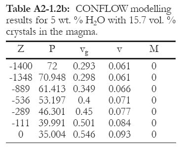
Display large image of Table A2-1.2b
Table A2-1.3a: CONFLOW modelling results for 10 wt. % H2O with no crystals in the magma.
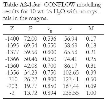
Display large image of Table A2-1.3a
Table A2-1.3b: CONFLOW modelling results for 10 wt. % H2O with 15.7 vol. % crystals in the magma.
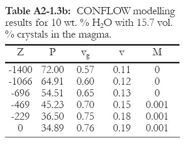
Display large image of Table A2-1.3b
Table A2-1.4a: CONFLOW modelling results for 12 wt. % H2O with no crystals in the magma.
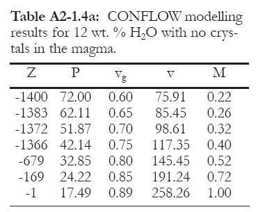
Display large image of Table A2-1.4a
Table A2-1.4b: CONFLOW modelling results for 12 wt. % H2O with 15.7 vol. % crystals in the magma.
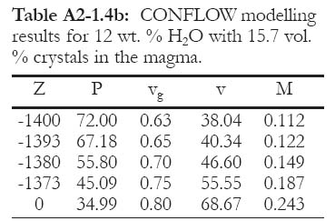
Display large image of Table A2-1.4b
Table A2-1.5a: CONFLOW modelling results for 15 wt. % H2O with no crystals in the magma.
Display large image of Table A2-1.5a
Table A2-1.5b: CONFLOW modelling results for 15 wt. % H2O with 15.7 vol. % crystals in the magma.
Display large image of Table A2-1.5b
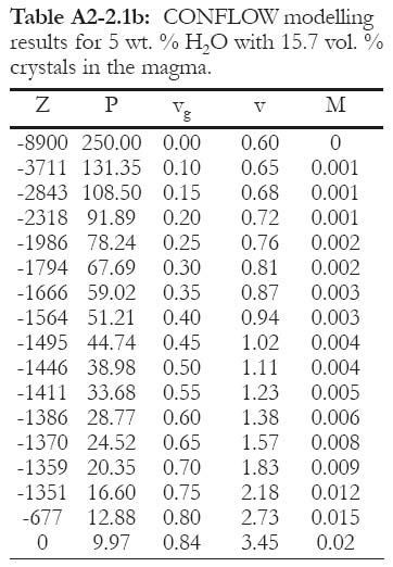
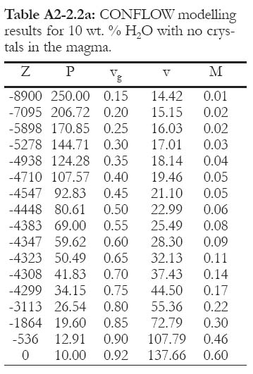
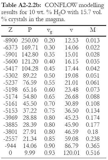
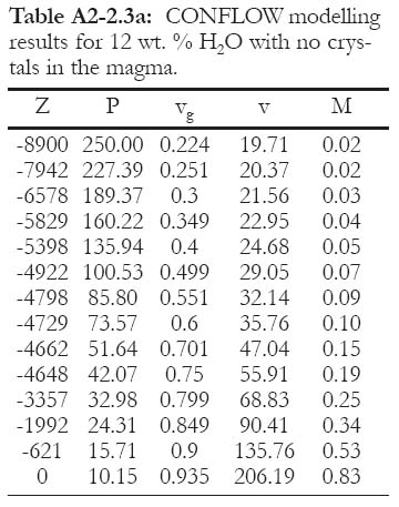
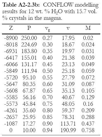
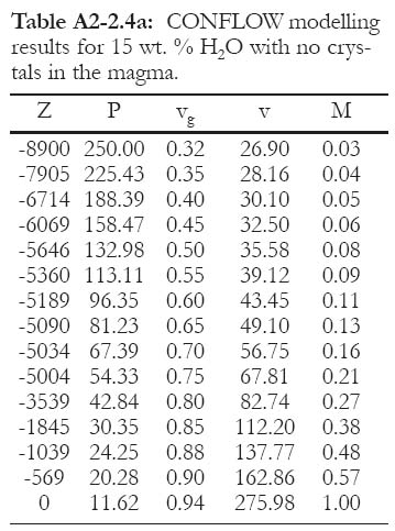
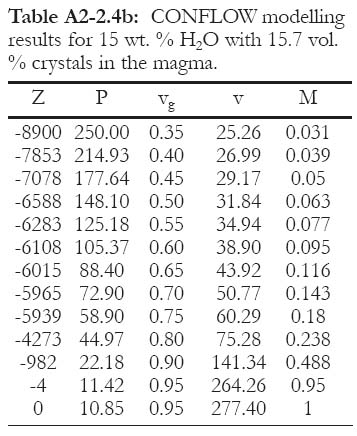
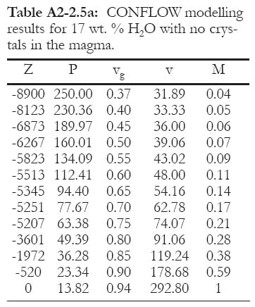
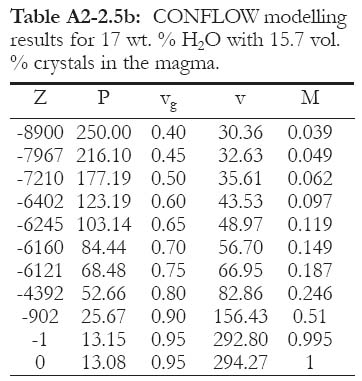
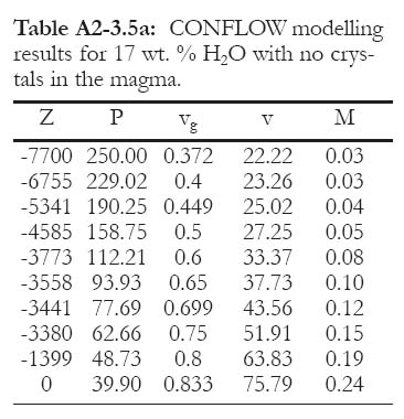
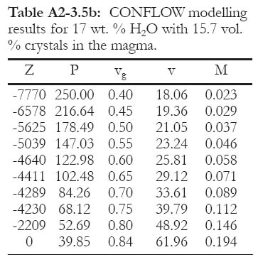
The second set of tables (A2-2) models an intermediate level magma chamber at 250 MPa, which corresponds to a lithostatic depth of 8.9 km underneath a 1.0 km water column. The results for an aphyric magma (a) and crystal rich magma (b) with five different water contents (5, 10, 12, 15, 17 wt. %) are shown.
Table A2-2.a: CONFLOW modelling results for 5 wt. % H2O with no crystals in the magma.
Display large image of Table A2-2.a
Table A2-2.1b: CONFLOW modelling results for 5 wt. % H2O with 15.7 vol. % crystals in the magma.
Display large image of Table A2-2.1b
Table A2-2.2a: CONFLOW modelling results for 10 wt. % H2O with no crystals in the magma.
Display large image of Table A2-2.2a
Table A2-2.2b: CONFLOW modelling results for 10 wt. % H2O with 15.7 vol. % crystals in the magma.
Display large image of Table A2-2.2b
Table A2-2.3a: CONFLOW modelling results for 12 wt. % H2O with no crystals in the magma.
Display large image of Table A2-2.3a
Table A2-2.3b: CONFLOW modelling results for 12 wt. % H2O with 15.7 vol. % crystals in the magma.
Display large image of Table A2-2.3b
Table A2-2.4a: CONFLOW modelling results for 15 wt. % H2O with no crystals in the magma.
Display large image of Table A2-2.4a
Table A2-2.4b: CONFLOW modelling results for 15 wt. % H2O with 15.7 vol. % crystals in the magma.
Display large image of Table A2-2.4b
Table A2-2.5a: CONFLOW modelling results for 17 wt. % H2O with no crystals in the magma.
Display large image of Table A2-2.5a
Table A2-2.5b: CONFLOW modelling results for 17 wt. % H2O with 15.7 vol. % crystals in the magma.
Display large image of Table A2-2.5b
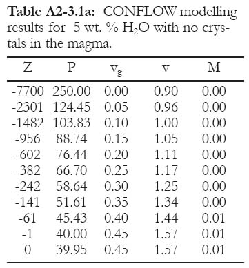
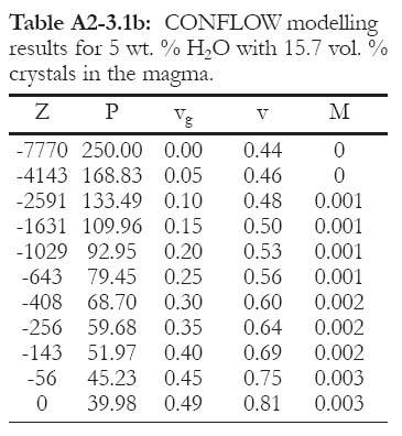
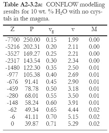
The third set of tables (A2-3) models an intermediate level magma chamber at 250 MPa, which corresponds to a lithostatic depth of 7.77 km underneath a 4.0 km water column. The results for an aphyric magma (a) and crystal rich magma (b) with five different water contents (5, 10, 12, 15, 17 wt. %) are shown.
Table A2-3.1a: CONFLOW modelling results for 5 wt. % H2O with no crystals in the magma.
Display large image of Table A2-3.1a
Table A2-3.1b: CONFLOW modelling results for 5 wt. % H2O with 15.7 vol. % crystals in the magma.
Display large image of Table A2-3.1b
Table A2-3.2a: CONFLOW modelling results for 10 wt. % H2O with no crystals in the magma.
Display large image of Table A2-3.2a
Table A2-3.2b: CONFLOW modelling results for 10 wt. % H2O with 15.7 vol. % crystals in the magma.
Display large image of Table A2-3.2b
Table A2-3.3a: CONFLOW modelling results for 12 wt. % H2O with no crystals in the magma.
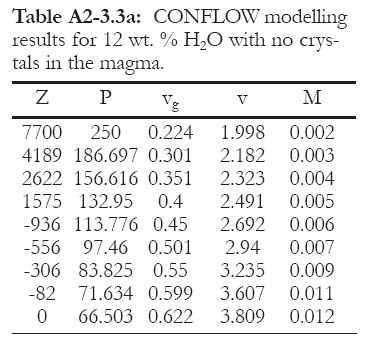
Display large image of Table A2-3.3a
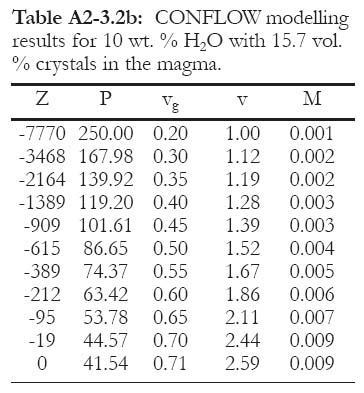
Table A2-3.3b: CONFLOW modelling results for 12 wt. % H2O with 15.7 vol. % crystals in the magma.
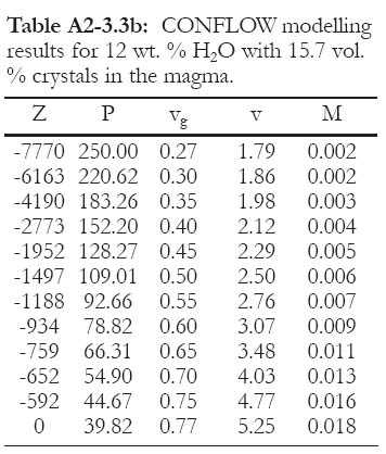
Display large image of Table A2-3.3b
Table A2-3.4a: CONFLOW modelling results for 15 wt. % H2O with no crystals in the magma.
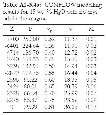
Display large image of Table A2-3.4a
Table A2-3.4b: CONFLOW modelling results for 15 wt. % H2O with 15.7 vol. % crystals in the magma.
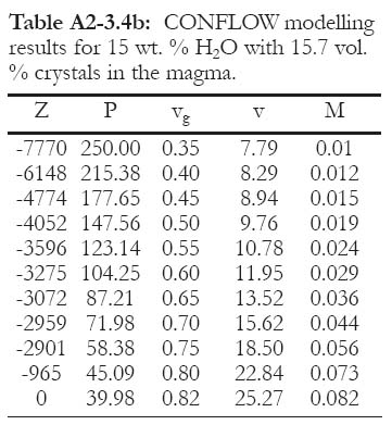
Display large image of Table A2-3.4b
Table A2-3.5a: CONFLOW modelling results for 17 wt. % H2O with no crystals in the magma.
Display large image of Table A2-3.5a
Table A2-3.5b: CONFLOW modelling results for 17 wt. % H2O with 15.7 vol. % crystals in the magma.
ACKNOWLEDGEMENTS
This research was supported by an NSERC Discovery Grant to D.R. Lentz at the University of New Brunswick. This project is a contribution to IGCP 502 Project. Many thanks must go to C. Shaw for many discussions and advice on the development of the manuscript. Thanks to C. Busby, A. Soule and R. S. Fiske for their helpful revisions and insightful comments in reviewing this manuscript.REFERENCES
Allen, R. L. and Cas, R. A. F., 1990, The Rosebury controversy: distinguishing prospective submarine ignimbrite-like units from true subaerial ignimbrites in the Rosebury-Hercules Zn-Cu-Pb massive sulfide district, Tasmania: Geological Society of Australia Abstracts, v. 25, p. 31-32.
Alidibirov, M. A. and Dingwell, D. B., 1996, Magma fragmentation by rapid decompression: Nature, v. 380, p. 146-148.
Alidibirov, M. A. and Panov, V. K., 1994, Fragmentation of highly viscous magmas during volcanic blasts; laboratory simulations: International Geological Congress Abstracts, v. 29, p. 493.
Blank, J. G., Stolper, E., and Carroll, M. R., 1993, Solubilities of carbon dioxide and water in rhyolitic melt at 850°C and 750 bars: Earth and Planetary Science Letters, v. 119, p. 27-36.
Bloomer, S. H., Stern, R. J., and COOK 17 Shipboard Party, 2001, Mantle inputs to the subduction factory: Detailed studies of the southern Marian seamount province: EOS, Transactions American Geophysical Union, v. 82, no. 47, Fall Meeting Supplement, F1201-1202.
Burnham, C. W., 1967, Hydrothermal fluids at the magmatic stage, in Barnes, H. L., ed. Geochemistry of Hydrothermal Ore Deposits: New York, Holt, Rinehart and Winston, p. 34-76.
Burnham, C. W., 1979, The importance of volatile constituents, in Yoder Jr., H.S., ed. The Evolution of Igneous Rocks, New Jersey: Princeton University Press,p. 439-582.
Burnham, C. W., 1983, Deep submarine pyroclastic eruptions: Economic Geology Monograph, v. 5, p. 142-148.
Busby, C. J., 2005, Possible distinguishing characteristics of very deepwater explosive and effusive silicic volcanism: Geology, v. 33, p. 845-848.
Busby, C. J., Kessel, L., Schulz, K. J., Foose, M. P., and Slack, J. F., 2003, Volcanic setting of the Ordovician Bald Mountain massive sulfide deposits, northern Maine, in Goodfellow, W. D., McCutcheon, S. R., and Peter, J. M., eds. Massive Sulphide Deposits of the Bathurst Mining Camp, New Brunswick, and Northern Maine: Economic Geology Monograph 11, p. 210-244.
Carlisle, D., 1963, Pillow breccias and their aquagene tuffs, Quadra Island, British Columbia: Journal of Geology, v. 71, p. 48-71.
Carroll, M. R. and Webster, J. D., 1994, Solubilities of sulfur, noble gases, nitrogen, chlorine, and fluorine in magmas, in Carroll, M. R. and Holloway, J.R., eds. Volatiles in Magmas: Reviews in Mineralogy, v. 30, p. 231-279.
Cas, R.A.F., 1992, Submarine volcanism: eruption styles, products and relevance to understanding the host-rock successions to volcanic-hosted massive sulphide deposits: Economic Geology, v.87, p. 511-541.
Cas, R. A. F. and Wright, J. V., 1987, Volcanic Successions: Modern and Ancient: London, Allen and Unwin, 529 p.
Cashman, K. V., Sturtevant, B., Papale, P., and Navon, O., 2000, Magmatic fragmentation, in Sigurdsson, H., Houghton, B.F., Mc Nutt, S.R., Rymer, H., and Stix, J., eds., Encyclopedia of Volcanoes: San Diego, Academic Press, p. 421-430.
Dobran, F., 1992, Nonequilibrium flow in volcanic conduits and application to the eruptions of Mt. St. Helens on May 18, 1980 and Vesuvius in AD 79: Journal of Volcanology and Geothermal Research,v. 49, p. 285-311.
Downey, W.S., 2005, The geological setting, petrology and facies analysis of the Nepisiguit Falls Formation, Bathurst Mining Camp: An example of a deep submarine pyroclastic eruptive sequence: Unpublished M.Sc. Thesis, University of New Brunswick, Fredericton, New Brunswick, 309p.
Eichelberger, J. C. and Hayes, D. B., 1982, Magmatic model for the Mount St. Helens blast of May 18, 1980: Journal of Geophysical Research, v. 87, p. 7727-7738.
Fine, G. J. and Stolper, E. M., 1986, Dissolved carbon dioxide in basaltic glasses: Concentrations and speciations: Earth and Planetary Science Letters, v. 76, p. 263-278.
Fisher, R. V. and Schmincke, H. U., 1984, Pyroclastic Rocks: Berlin, Springer-Verlag, 472 p.
Fiske, R. S. and Matsuda, T., 1964, Submarine equivalents of ash flows in the Towkiwa Formation, Japan: American Journal Science, v. 262, p. 76-106.
Fiske, R. S., Naka, J., Iizasa, K., Yuasa, M., and Klaus, A., 2001, Submarine silicic caldera at the front of the Izu-BoninArc, Japan: voluminous seafloor eruptions of rhyolite pumice: Geological Society of America Bulletin, v. 113, p. 813-824.
Fogel, R. A. and Rutherford, M. J., 1990, The solubility of carbon dioxide in rhyolitic melts: A qualitative FTIR study: American Mineralogist, v. 75, p. 1311-1326.
Foley, N. K., 2003, Thermal and chemical evolution of ore fluids and massive sulfide mineralization at Bald Mountain, Maine, in Goodfellow, W. D., McCutcheon, S. R., and Peter, J. M., eds., Massive Sulphide Deposits of the Bathurst Mining Camp, New Brunswick, and Northern Maine: Economic Geology Monograph 11, p. 549-566.
Gardner, J., Tait, S., Jaupart, C., and Thomas, R., 1996, Fragmentation of magma during explosive volcanic eruptions; the pumice record: EOS, Transactions American Geophysical Union, v. 77, no. 46, p. 818.
Gardner, J. E., Hilton, M., and Carroll, M.R., 1999, Experimental constraints on degassing of magma: isothermal bubble growth during continuous decompression from high pressure: Earth and Planetary Science Letters, v. 168, p. 201-218.
Gibson, H. L., Morton, R. L., and Hudak, G.L., 1999, Submarine volcanic processes, deposits and environments favorable for the location of volcanic-associated massive sulphides deposits, in Barrie, T. and Hannington, H., eds., Volcanic-associated massive sulphide deposits: Processes and examples in modern and ancient settings: Reviews in Economic Geology, v. 8,p.13-51.
Gilbert, J. S. and Sparks, R. S. J., 1998, The Physics of Explosive Eruptions: Geological Society, London, Special Publication v. 145, 186 p.
Gonnermann, H. M. and Manga, M., 2003, Explosive volcanism may not be an inevitable consequence of magma fragmentation: Nature, v. 426, p. 432-435.
Guber , A. L. and Merrill, S. M. I., 1983, Paleobathymetric significance of foraminifera from the Hokuroko district, in Ohmoto, H. and Skinner, B. J., eds., The Kuroko and Related Volcanic Massive Sulfide Deposits: Economic Geology Monograph 5, p. 55-70.
Gudmundsson, M.T., 2003, Melting of ice by magma-ice-water interactions during subglacial eruptions as an indicator of heat transfer in subaqueous eruptions, in White, J., Smellie, J. and Claugue, D., eds. Explosive Subaqueous Volcanism: American Geophysical Union, Geophysical Monograph Series, v. 140, p. 61-72.
Head, J. W. and Wilson, L., 2003, Deep submarine pyroclastic eruptions: theory and predicted landforms and deposits: Journal of Volcanology and Geothermal Research, v. 121, p. 151-193.
Hess, K.-U. and Dingwell, D. B., 1996, Viscosities of hydrous leucogranitic melts: A non-Arrhenian model: American Mineralogist, v. 81, p. 1297-1300.
Hildreth, W. and Drake, R. E., 1992, Volcan Quizapu, Chilean Andes: Bulletin of Volcanology, v. 54, p. 93-125.
Holloway, J. R. and Blank, J. G., 1994, Application of experimental results to C-O-H species in natural melts, in Carroll, M. R. and Holloway, J.R., eds. Volatiles in Magmas: Reviews in Mineralogy, v. 30, p. 187-230.
Hurwitz, S. and Navon, O., 1994, Bubble nucleation in rhyolitic melts: experiments at high pressures, temperatures and water content: Earth and Planetary Science Letters, v. 122, p. 267-280.
Jaupart, C., 1996, Physical models of volcanic eruptions: Chemical Geology, v. 128, p. 217-227.
Kilinic, I. A. and Burnham, C. W., 1972, Partitioning of chloride between a silicate melt and coexisting aqueous phase from 2 to 8 kilobars: Economic Geology,v. 67, p. 231-235.
Klug, C. and Cashman, K. V., 1994, The development of permeability in pumice: EOS, Transactions American Geophysical Union, v. 75, no. 44, p. 702.
Kokelaar, B. P., 1986, Magma-water interactions in subaqueous and emergent basaltic volcanism: Bulletin of Volcanology, v. 48, p. 275-289.
Koster van Groos, A. F. K. and Wyllie, P. J., 1969, Melting relationships in the system NaAlSi3O8-NaCl-H2O at one kilobar pressure, with petrological applications: Journal of Geology, v. 77, p. 581-605.
Kotlova, A. G., Ol'shanskii, Y. I., and Tsvetkov, A. I., 1960, Some trends in immiscibility effects in binary silicate and borate systems: Mineralogiya i Geokhimiya Trudi Instituta Geologii Rudnikh Mestorojdenii, AN SSSR, v. 42,p. 3.
Kravchuk, I. F., Malinin, S. D., and Senin, V.G., 1998, Solubility of chlorine in aluminosilicate melts: Geochemistry International, v. 36, p. 958-963.
Lentz, D.R., Walker. J., and McCutcheon, S.R., 1999, Pyroclastic volcanism and VMS deposit genesis: resolving the depth dilemma: GAC-MAC Joint Annual Meeting, Abstract Volume 24, p. 69.
Lowenstern, J. B., 2001, Carbon dioxide in magmas and implications of hydrothermal systems: Mineralium Deposita, v. 36,p. 490-502.
Lyakhovsky, V., Hurwitz, S., and Navon, O., 1996, Bubble growth in rhyolitic melts: experimental and numerical investigation: Bulletin of Volcanology, v. 58, p. 19-32.
Malinin, S. D., Kravchuk, I. F., and Delbove, F., 1989, Chlorine distribution between phases in hydrated and dry chloride-aluminosilicate melt systems as a function of phase composition: Geochemistry International, v. 26, p. 38.
Mangan, M., Mastin, L., and Sisson, T., 2004, Gas evolution in eruptive conduits: combining insights from high temperature and pressure decompression experiments with steady-state flow modeling: Journal of Volcanology and Geothermal Research, v. 129, p. 23-36.
Martel, C., Dingwell, D. B., Spieler, O., Pichavant, M., and Wilke, M., 2001, Experimental fragmentation of crystal-and vesicle-bearing silicic melts: Bulletin of Volcanology, v. 63, p. 398-405.
Mastin, L. G. and Ghiorso, M. S., 2000, A numerical program for steady-state flow of magma-gas mixtures through vertical eruptive conduits: USGS Open-File Report 00-209, 53 p.
McPhie, J., Doyle, M. G., and Allen, R. L., 1993, Volcanic Textures: Hobart, CODES, University of Tasmania, 198 p.
Moore, J. G., 1965, Petrology of deep-sea basalt near Hawaii: American Journal Science, v. 263, p. 40-52.
Moore, J. G., Phillips, R. L., Grigg, R. W., Peterson, D. W., and Swanson, D. A., 1973, Flow of lava into the sea 1969-1971, Kilauea Volcano, Hawaii: Geological Society of America Bulletin,v. 84, p. 537-546.
Mourtada-Bonnefoi, C. C. and Laporte, D., 2004, Kinetics of bubble nucleation in a rhyolitic melt: an experimental study of the effect of ascent rate: Earth and Planetary Science Letters, v. 218, p. 521-537.
Murase, T. and McBirney, A. R., 1973, Properties of some common igneous rocks and their melts at high temperatures: Geological Society of America Bulletin, v. 84, p. 3563-3592.
Navon, O. and Lakhovsky, V., 1998, Vesiculation processes in silicic magmas, in Gilbert, J.S. and Sparks, R.J.S., eds. The Physics of Explosive Volcanic Eruptions: Geological Society, London, Special Publication v. 145, p. 27-50.
Ohmoto, H., 1978, Submarine calderas: A key to the formation of volcanogenic massive sulphide deposits?: Mining Geology, v. 28, p. 219-231.
Papale, P., 1999, Modelling of magma ascent in volcanoes: EOS, Transactions American Geophysical Union, v. 80, no. 46, p. 1084-1085.
Papale, P., Neri, A., and Macedonio, G., 1998, The role of magma composition and water in explosive eruptions 1. Conduit ascent dynamics: Journal of Volcanology and Geothermal Research,v. 87, p. 75-93.
Proussevitch, A. A. and Sahagian, D. L., 1996, Dynamics of coupled diffusion and decompressive bubble growth in magmatic systems: Journal of Geophyical Research, v. 101, p. 17447-17455.
Proussevitch, A. A. and Sahagian, D. L., 1998, Dynamics and energetics of bubble growth in magmatic systems: Journal of Geophyical Research, v. 103, p. 18223-18225.
Proussevitch, A. A., Sahagian, D. L., and Anderson, A. T., 1993, Dynamics of bubble growth in magmas: isothermal case: Journal of Geophyical Research, v. 98, p. 22283-22307.
Roedder, E., 1984, Fluid Inclusions: Mineralogical Society of America, Reviews in Mineralogy 12, 644 p.
Rubie, D. C., Ross, C. R. II., Carroll, M. R., and Elphick, S. C., 1993, Oxygen self-diffusion in Na2Si4O9 liquid up to 10 GPa and estimation of high pressure viscosities: American Mineralogist, v. 78, p. 574-582.
Ryabchikov, I. D., 1963, Experimental study of the distribution of alkali elements between immiscible silicate and chloride melts: Doklady Akademii Nauk SSSR, v. 149, p. 190-192.
Schneider, J.-L., 2000, Volcaniclastic sedimentation in submarine settings: products and processes: Amsterdam, Gordon and Breasch Science Publisher, p. 175-192.
Shinohara, H., Ilyama, J. T., and Matsuo, S., 1989, Partitioning of chloride compounds between silicate melt and hydrothermal solutions: Geochimica et Cosmochimica Acta, v. 53, p. 2617-2630.
Sourirajan, S. and Kennedy, G. C., 1962, The system H2O-NaCl at elevated temperatures and pressures: American Journal Science, v. 260, p. 115-141.
Sparks, R. S. J., 1978, The dynamics of bubble formation and growth in magmas: a review and analysis: Journal of Volcanology and Geothermal Research, v. 3, p. 1-37.
Sparks, R. S. J., Barclay, J., Jaupart, C., Mader,H. M., and Phillips, J. C., 1994, Physical aspects of magma degassing; 1. Experimental and theoretical constraints on vesiculation, in Carroll, M.R. and Holloway, J.R., eds. Volatiles in Magmas: Reviews in Mineralogy, v. 30, p. 413-445.
Stix, J., 1991, Subaqueous, intermediate to silicic-composition explosive volcanism: a review: Earth Science Reviews, v. 31, p. 21-53.
Stolper, E., 1982, Water in silicate glasses: an infrared spectroscopic study: Contributions to Mineralogy and Petrology, v. 81, p. 1-17.
Stolper, E., 1989, Temperature dependence of the speciation of water in rhyolitic melts and glasses: American Mineralogist, v. 74, p. 1274-1257.
Thorarinsson, S., 1967, Surtsey: The New Island in the North Atlantic: New York, Viking Press, 47 p.
Tourmaru, A., 1995, A numerical study of nucleation and growth of bubbles in viscous magmas: Journal of Geophysical Research, v. 100, p. 1913-1931.
Wallace, P. and Anderson, A. T., Jr., 2000, Volatiles in magmas, in Sigurdsson, H., Houghton, B.F., Mc Nutt, S.R., Rymer,H., and Stix, J., eds., Encyclopedia of Volcanoes: San Diego, Academic Press,p. 149-170.
Webster, J. D. and Holloway, J. R., 1988, Experimental constraints on the partitioning of Cl between topaz rhyolite melt and H2O and H2O + CO2 fluids: New implications for granitic differentiation and ore deposition: Geochimica et Cosmochimica Acta, v. 52, p. 2091-2105.
Whitney, J. A., 1989, Origin and evolution of silicic magmas, in Whitney, J. A. and Naldrett, A. J., eds. Ore Deposition Associated with Magmas: Reviews in Economic Geology, v. 4, p. 183-202.
Williams, H. and McBirney, A. R., 1979, Volcanology: San Francisco, Freeman, Cooper and Co., 397 p.
Wohletz, K. H., 2003, Water/magma interaction: physical considerations for the deep submarine environment, in White, J.D.L., Smellie, J.L. and Clague, D.A., eds. Explosive Subaqueous Volcanism: American Geophysical Union, Geophysical Monograph Series, v. 140, p. 25-50.
Worthington, T. J., Gregory, M. R., and Bondarenko., V., 1999, The Denham caldera on Raoul Volcano, dacite volcanism in the Tonga-Kermadec arc: Journal Volcanology and Geothermal Research,v. 90, p. 29-48.
Wright, I. C., de Ronde, C .J. E., Faure, K., and Gamble, J., 1998, Discovery of hydrothermal sulfide mineralization from southern Kermadec arc volcanoes (SW Pacific): Earth and Planetary Science Letters, v. 164, p. 355-343.
Wright, I. C., Gamble, J. A., and Shane, P. A.R., 2003. Submarine silicic volcanism of the Healy caldera, southern Kermadec arc (SW Pacific): 1 – volcanology and eruption mechanisms: Bulletin of Volcanology, v. 65, p. 15-29.
Yuasa, M. and Kano, K., 2003, Submarine silicic calderas on the northern Shichito-Iwojima Ridge, Izu-Ogasawara (Bonin) arc, western Pacific, in White, J.D.L., Smellie, J. L. and Clague, D. A., eds. Explosive Subaqueous Volcanism: American Geophysical Union, Geophysical Monograph Series, v. 140, p. 231-244.
Zettlemoyer, A. C., 1969, Nucleation: NewYork, 606 p.