Series
Remote Predictive Mapping 2.
Gamma-Ray Spectrometry: A Tool for Mapping Canada's North
K. FordGeological Survey of Canada
601 Booth Street
Ottawa, ON, Canada, K1A 0E9
kford@nrcan.gc.ca
J. R. Harris
GamX
308 Edward Scott Road
Mountain, ON, Canada, K0E 1S0
gamx@qsat.ca
R. Shives
Geological Survey of Canada
601 Booth Street
Ottawa, ON, Canada, K1A 0E9
J. Carson
Geological Survey of Canada
601 Booth Street
Ottawa, ON, Canada, K1A 0E9
J. Buckle
Geological Survey of Canada
601 Booth Street
Ottawa, ON, Canada, K1A 0E9
Submitted June, 2008. Accepted as revised November, 2008
SUMMARY
This paper reviews the theory, acquisition and application of gamma-ray spectrometric data for geological mapping, especially for Canada's North. Theoretical principals are reviewed and survey parameters and data acquisition procedures are discussed. Interpretation principles are then presented and various methods, utilizing computer processing, enhancement and classification procedures are introduced using many image examples.The ability of gamma-ray spectrometry to map the distribution of potassium, uranium, and thorium on the surface of the Earth provides powerful assistance for regional and local bedrock and surficial geological mapping. Important direct and indirect exploration guidance, in a wide variety of geological settings, is also provided, as is important information for environmental radiation monitoring and land-use planning.
SOMMAIRE
Le présent article passe en revue les fondements théoriques, l'acquisition et l'application des données spec-trométriques du rayonnement gamma comme outil de cartographie géologique, particulièrement pour le Nord canadien. On y examine les principes théoriques et on y discute des paramètres de levé et des méthodes d'acquisition des données. Puis, on y présente les principes et diverses méth-odes d'interprétation, utilisant le traitement de rehaussement et de classification par ordinateur, à partir de nombreux exemples d'images.La cartographie de la distribution du potassium, de l'uranium, et du thorium à la surface de la Terre à partir de techniques de spectrométrie du rayonnement gamma est une aide précieuse pour la cartographie géologique de surface locale et régionale. Cette technique constitue aussi un important guide d'exploration direct et indirect, dans une large gamme de contextes géologiques, tout comme une importante source d'information pour le monitorage des radiations dans l'environnement et la planification de l'aménagement du territoire.
INTRODUCTION
1 All rocks and soils are naturally radioactive, containing various proportions of a variety of radioactive elements. The natural decay of these elements produces a variety of radiation types (alpha, beta, and gamma) at specific energy levels. Only gamma-ray radiation has sufficient range to be useful for airborne geophysical surveying, providing a method of measuring concentrations of individual radioactive elements (in particular potassium, uranium, and thorium) in support of bedrock and surficial geological mapping, exploration for a variety of mineral commodities, and for environmental radiation monitoring. Airborne gamma-ray spectrometric (AGRS) surveys provide valuable, systematic coverage of large areas, whereas ground gamma-ray spectrometry (GGRS) greatly improves the resolution of individual radioactive element sources.
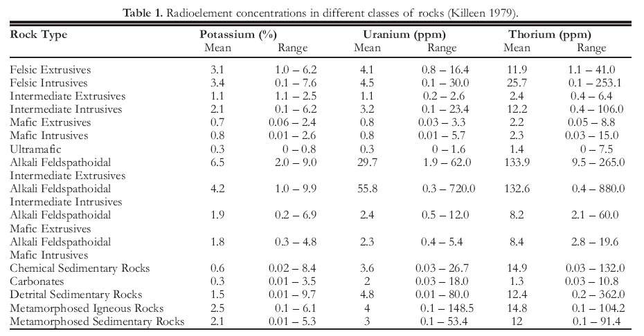
2 Gamma rays are released through the spontaneous decay of radioactive elements. The three most common, naturally occurring radioactive elements are potassium, uranium, and thorium, which are found in varying concentrations in most rock-forming minerals. Potassium occurs mainly in the mineral feldspar, which is an abundant and widespread mineral in the Earth's crust. It also occurs in other common rock-forming minerals, such as biotite and muscovite. Uranium and thorium are generally present in low concentrations (measured in parts per million, ppm) in a wide range of minerals. The range of radioactive element concentrations in most common rock types is shown in Table 1 (Killeen 1979).
3 Directly or indirectly, these three radioactive elements can provide an indication of economic concentrations of many other metals. For example, high concentrations of uranium may directly represent a target of economic interest, but may also be used as indirect indicators of other types of mineralization if they occur as trace elements associated with that mineralization, or if they are enriched or depleted due to alteration. For example, gamma-ray surveys are effective in mapping potassic alteration associated with certain mineral deposit types, including porphyry Cu (–Au–Mo), volcanogenic massive sulphide and iron-oxide–copper–gold (IOCG; Shives et al. 1997). Maps that show radioactive element distribution provide information about fundamental mineralogical and geochemical properties of bedrock and surficial deposits, and have proven highly useful for geological mapping, mineral exploration, and environmental studies, often indicating geological features not seen by other techniques.
Table 1. Radioelement concentrations in different classes of rocks (Killeen 1979).
Display large image of Table 1
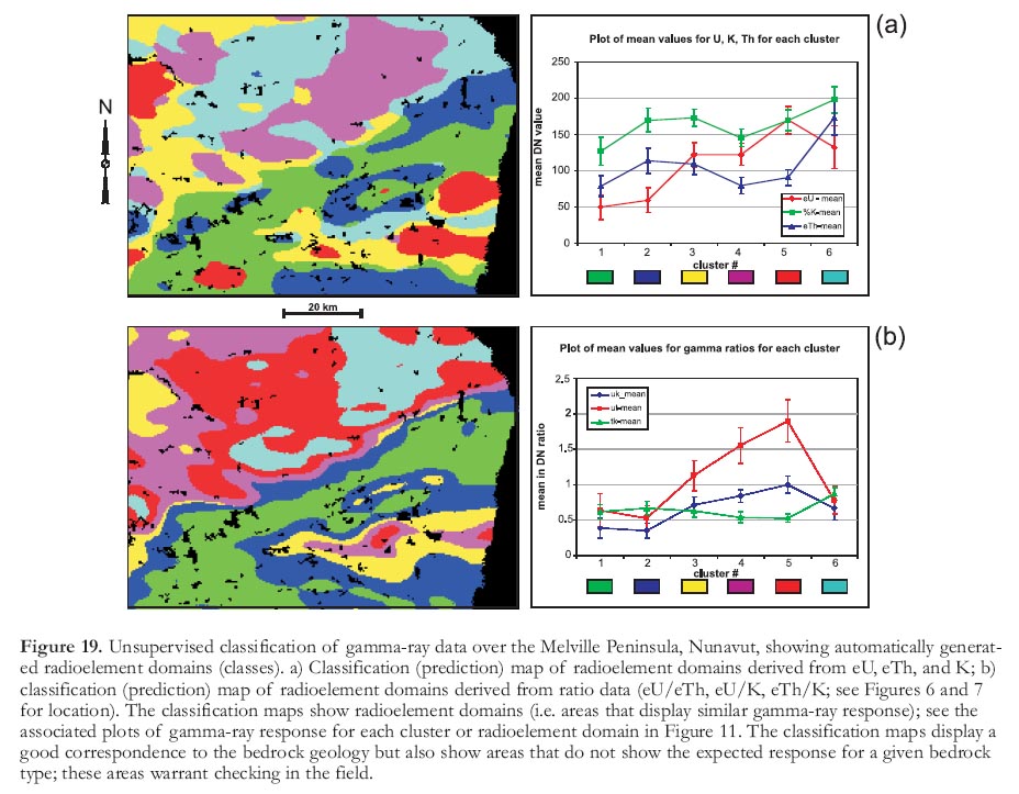
4 Gamma-ray spectrometry (GRS) is a surface technique only, providing a direct measurement of radioactive element concentrations at the surface of the Earth. There is no significant depth of penetration because the source of most gamma radiation is limited to the top 0.30 m of the Earth's surface. This surface-only characteristic allows geologists to reliably relate the measured radioactive element contrasts to the subjacent bedrock and surficial materials, and alteration associated with mineral deposits. All rocks, and the materials derived from them, are radioactive, containing detectable amounts of a variety of radioactive elements. A gamma-ray spectrometer is designed to detect the gamma rays associated with these radioactive elements and to accurately sort the detected gamma rays by their respective energies. It is this sorting ability that distinguishes the spectrometer from instruments that measure only total radioactivity, e.g. scintillometers.
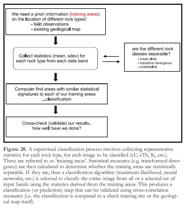
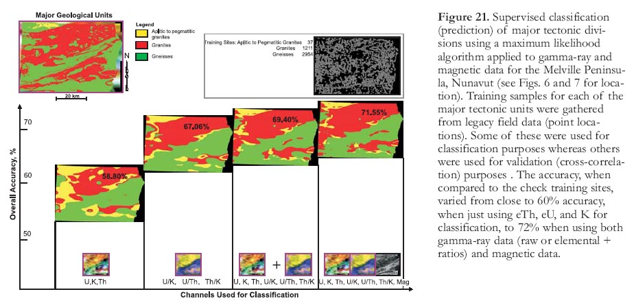
THE GAMMA-RAY ENERGY SPECTRUM
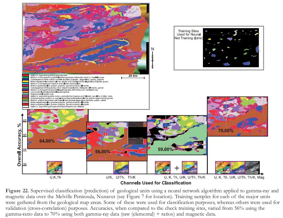
5 Data acquired by gamma-ray spectrometric methods are normally portrayed as a multi-channel gamma-ray energy spectrum. A typical natural radiation energy spectrum (Fig. 1) depicts the relative count rates at each energy level from 0 to 3 mega-electron volts (MeV). The interval from 0 to 0.4 MeV is not used because it is dominated by Compton scattering of higher energy radiation (Grasty 1979). For geological mapping, the 40K (potassium), bismuth-214 (214Bi, a decay product of uranium), and thallium-208 (208Tl, a decay product of thorium) peaks are of interest. Concentrations of uranium and thorium are determined indirectly from their daughter products (214Bi and 208Tl, respectively), which are assumed to be in equilibrium with their parent isotope. Potassium concentration is determined directly from 40K. The term 'equivalent' or the abbreviation 'e' is used for reporting concentrations of uranium and thorium determined by gamma-ray spectrometry. During an airborne survey, the full spectrum is recorded once per second, using a 256-channel histogram. During post-flight data processing, the counts for the radioelements of interest (i.e. 40K, 214Bi, 208Tl) are accumulated; this summation includes the counts for a range of energies (a 'window' or 'region of interest') centred on each peak. The standard energy windows are shown in Table 2. For presentation purposes, the accumulated count rates are converted to equivalent ground concentrations of potassium, uranium, and thorium using a set of calibration constants unique to the spectrometer system being used.
Figure 1. Typical gamma-ray spectrometry energy windows.AIRBORNE GAMMA-RAY SPECTRO-METRIC SURVEYS
6 Airborne geophysical surveys are normally flown in a direction perpendicular to the main geological strike of the survey area. For AGRS surveying, the line spacing depends on the objectives of the survey: in reconnaissance surveys it may vary between 2000 and 5000 m; in regional surveys it may vary between 500 and 2000 m; and in detailed surveys flown for mineral exploration purposes, flight line spacing can be as little as 100 or 200 m. The above-ground flight elevation (terrain clearance) in fixed-wing spectro-metric surveys is normally 120 m, although it may vary between 100 and 150 m. For helicopter-borne surveys, the detectors are mounted in the helicopter, and the nominal terrain clearance varies between 60 and 120 m, depending on local terrain conditions and the configuration of other survey equipment. Typically, aircraft fly at a speed of approximately 120 knots (190 km/h).
Table 2. Typical gamma-ray spectrometry energy windows.

Display large image of Table 2
7 A typical gamma-ray system includes a 256-channel spectrometer that records data at 1-second intervals, which is equivalent to about 60 m on the ground. Surveys flown with a fixed-wing aircraft usually employ sensors consisting of 50 l of thallium-doped sodium iodide NaI(Tl) crystals in the main detector array, and 8 to 12 l of NaI(Tl) crystals in the upward-looking detector array. When using a helicopter platform, the main detector array will usually consist of 33 l of NaI(Tl) crystals, and the upward-looking array from 4 to 8 l. After energy calibration of the spectra, counts from the main detector are recorded in the five windows listed in Table 2. Radiation in the upward-looking detector is recorded in a radon window (1660– 1860 kilo-electron volts (keV)). Comprehensive descriptions of airborne and ground gamma-ray spectrometric surveys, including fundamentals, instrumentation, calibration, data processing, and interpretation, are presented by Grasty (1979), Grasty et al. (1991), Grasty and Minty (1995), Shives et al. (1995), Dickson and Scott (1997), Horsfall (1997), Minty (1997), Minty et al. (1997), Wilford et al. (1997), and the International Atomic Energy Agency (2003), and references therein.
8 Spectral enhancement techniques such as Noise Adjusted Singular Value Decomposition (NASVD) or Minimum Noise Fraction (MNF) can be used in GRS to improve the signal-to-noise ratio compared to recorded raw spectra (International Atomic Energy Agency 2003). These spectral-enhancement techniques impose rigorous constraints on the means of measuring raw spectra (see Grasty and Minty 1995). The use of these techniques will not change the average response for an area but will reduce the noise in individual readings. It has been estimated (Hovgaard and Grasty 1997) that NASVD yields an improvement similar to that obtained by increasing the detector volume by a factor of between three and four.
9 Constants such as stripping ratios, attenuation coefficients, and sensitivities must be carefully determined for each acquisition system. Proper application of these constants during processing usually results in seamless datasets across individual survey boundaries, regardless of the acquisition system used. Over-water values should not be deleted from a dataset or set to zero, because such values contain useful data-quality information. The statistical nature of the GRS technique means that 'negative' concentrations are acceptable in low average count-rate areas. If background corrections are properly determined, and correctly applied, then radioactive element concentrations should yield a mean concentration of zero over large bodies of water.
10 Radioelement ratios can offer a useful tool for lithological mapping. However, due to statistical uncertainties in the individual radioelement measurements, some care should be taken in the calculation of these radioelement ratios. Ratios should always be determined by using radioactive element concentrations because concentrations are computed using instrument-specific calibration constants, ensuring that results from other (calibrated) spectrometer systems will be consistent. An acceptable method of determining ratios neglects any data points for which the potassium concentration is less than a predetermined threshold, usually 0.25%, as these measurements are likely to have been collected over water. Next, the element concentrations of pairs of adjacent points on either side of the data point are progressively summed until the total accumulated concentration in both the numerator and denominator exceed values equivalent to at least 100 counts prior to conversion to concentrations. The ratios are then calculated using the accumulated sums of concentration values. With this method, the errors associated with the calculated ratios will be similar for all data points.
DATA SOURCES
11 Most of the airborne GRS data for Canada were collected through a variety of federal and federal/provincial cooperative programs to support ongoing and future geological mapping and mineral resource exploration activities. For these reasons, survey areas were typically chosen because of their high mineral potential. Systematic AGRS data have been acquired from about 1970 to the present, using a variety of aircraft and instrument packages. Figure 2 shows an index map of AGRS coverage for Canada.
12 Gamma ray spectrometric data for Canada are easily accessible through the internet using the Geo-science Data Repository (GDR) at [http://gdr.nrcan.gc.ca]. These data are derived from the digital archives of the Radiation Geophysics Section. Locations of the original flight lines and gridded data for over 300 surveys are currently available from the GDR web-site. Grids of Canada at 250 m cell size, using all digitally archived survey data, are also available from the GDR website. More information regarding the collection, distribution, and applications of GRS data can be found by visiting the Radiation Geophysics web-site at [http://gsc.nrcan.gc.ca/gamma].
INTERPRETATION
13 Unlike conventional magnetic, electromagnetic, gravity, and seismic techniques that measure physical rock properties (often in response to induced effects), and that may detect variations from source depths of tens to thousands of metres, AGRS and GGRS measure variations in radioactivity emanating from the top 0.30 m of the Earth's surface. The three most abundant natural radioactive elements, potassium, uranium and thorium, occur as major, mobile and immobile elements, respectively, in varying proportions, in all rocks and soils.
14 Because the concentration of each radioactive element varies between different rock types, a gamma-ray spectrometer can be used to measure these variations and effectively map the different rock types. Where the normal radioactive signature is altered by a mineralizing process, the resulting alteration-related signature provides exploration guidance. Interpretation becomes complicated when these bedrock-related signatures become obscured by overlying transported surficial material or by extreme weathering effects. In Canada, extensive glaciation has mechanically reworked and transported bedrock-derived material. However, the resulting overburden usually reflects local bedrock chemistry. Only when the surficial material is composed predominantly of reworked material, such as glaciofluvial or glaciolacustrine deposits, does the resulting radioactivity signature not reflect the underlying bedrock. Effective interpretation, therefore, requires some knowledge not only of the radioactive element contents of rock types expected to be found in the survey area, but also knowledge of the glacial history of that area.
15 Interpretation of AGRS data requires understanding of some basic concepts of gamma-ray spectrometry and the importance of proper controls on system calibration, data acquisition, data processing, and presentation methods. Some basic concepts are listed here:
- AGRS is a remotely sensed geophysical technique providing information about the distribution of K, U, and Th that is directly interpretable in terms of surface geology.
- AGRS is a surface technique only; interpretation requires an understanding of the nature of the surficial materials and their relationship to bedrock geology.
- Although AGRS measures a physical phenomenon, it is, for geological and exploration purposes, best considered in geochemical terms, i.e. as 'Airborne Geochemistry'.
- Unlike a camera lens, a gamma-ray spectrometer does not have a 'fixed field of view' – a highly radioactive point source may be detected even when it lies outside some nominal field of view.
- The gamma-ray flux decreases exponentially with distance from the source.
- A single AGRS measurement provides an estimate of the average surface concentration for an area of several thousand square metres; this area is commonly underlain by variable proportions of bedrock, overburden, soil moisture, open water, and vegetation.
- Typically, bedrock concentrations are higher than AGRS values, whereas concentrations in glacial drift are only slightly higher than AGRS values. However, AGRS ratios (eU/eTh, eU/K, and eTh/K) are normally a close approximation of those ratios at ground level.
- Ratio patterns can enhance subtle variations in elemental concentrations related to lithological changes or to alteration processes associated with mineralization.
- Not all ratio anomalies are created equal; caution should be used when interpreting ratio patterns, as questionable high-ratio anomalies can be generated by low count rates in the denominator.
16 The usefulness of AGRS in geological mapping and mineral exploration depends on two factors: 1) the extent to which radioelement distribution relates to bedrock differences and how this distribution may be modified by mineralizing processes; and 2) the extent to which bedrock radioelement content is reflected in surficial materials that can be spatially related to bedrock sources. Therefore, effective application of AGRS to geological mapping and mineral exploration must rely on knowledge of: i) how the acquired radioactive element distributions correlate with normal lithologic signatures; ii) how these normal litho-logic signatures are recognizably modified by mineralizing processes (alteration signatures); iii) how these litho-logical and alteration signatures are incorporated into surficial materials; and iv) how these surficial materials can be spatially related to bedrock sources. Remote predictive mapping (RPM) applications and methods should be directed toward improving our ability to address these four basic problems of effective AGRS interpretation.
Interpretation Issues
Resolution and Line Spacing
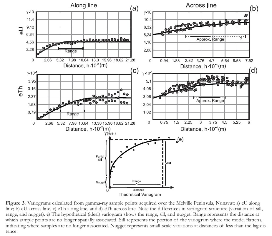
17 Airborne gamma-ray spectrometric data are collected along lines that are spaced anywhere from 5000 to less than 500 m apart. The data are densely sampled along the line, but sparsely sampled in the across-line direction, depending on the line spacing. This could potentially lead to problems in gridding (interpolating) the data, i.e. in creating a continuous image as opposed to a profile. The concept of spatial correlation comes into play, the term being a statistical one that can be simply defined as a measure of the tendency for places that are near to each other to have more similar or dissimilar values (positive or negative correlations, respectively). The problem can be summarized succinctly as follows: if there is little spatial correlation across each flight line, then interpolation of the data should not be undertaken. A variogram can be used to test whether spatial correlation exists, both along-line and across-line. Figure 3 shows variograms of AGRS data acquired with 5 km flight line spacing over the Melville Peninsula, Nunavut. Clearly, as might be expected, spatial correlation exists along the flight line with a range parameter from 500 to 1000 m (Fig. 3a, c). However, correlation also exists, albeit at much greater distances (approximately 25 000 to at least 40 000 m; Figs. 3b, d) across the line as well, indicating that, generally, gamma-ray data can be gridded (interpolated), even at 5000 m spacing. Spatial correlation also depends on the orientation of the flight line with respect to the regional geological strike (see Figs. 4, 5); e.g. spatial correlation will increase if the flight lines are parallel to the regional strike.
Figure 2. Index of airborne gamma-ray spectrometry coverage in Canada (September, 2008).

Display large image of Figure 2
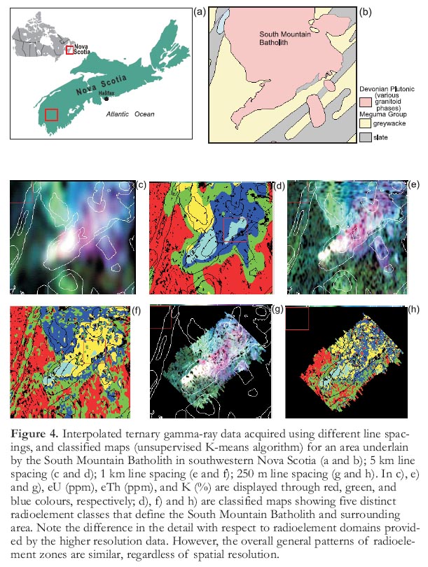
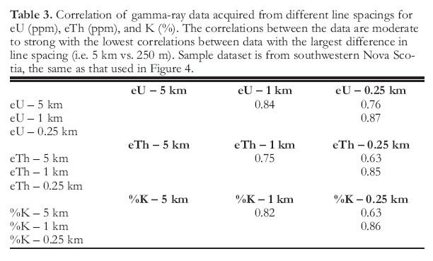
18 Like any other remote sensor, spatial resolution plays a significant role in determining how much geological detail can be extracted from the imagery, either in a visual sense or through the use of computer-processing techniques. With respect to gamma-ray data, this is clearly illustrated in Figure 4, which shows gridded, ternary images of an area in southwestern Nova Scotia at three different line spacings. It is interesting to note in this survey, which was flown over various phases of the South Mountain Batholith, that the same basic geological information (i.e. the major geological features) is available at a wider line spacing (lower resolution) as in higher resolution surveys with closer line spacings. In fact, the overall correlation between the images acquired at different line spacings is statistically similar (Table 3). The difference is a simple matter of detail. In fact, details of rapidly varying surface cover conditions, such as soil moisture and surface water, are often suppressed on lower resolution data, in which much of the response reflects regional bedrock patterns.
Grid versus Profile Data Presentations
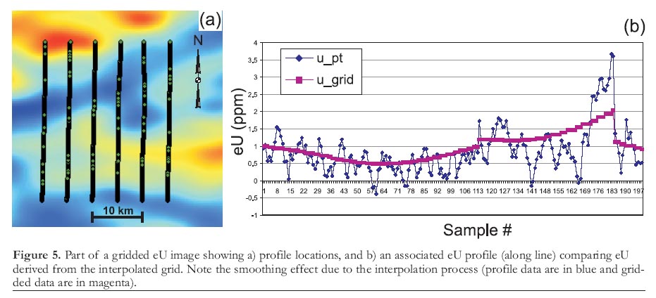
19 Gridded data are useful for regional mapping; however, due to the smoothing effect of the interpolation process, the detail offered by along-line profile data is much greater (Fig. 5). Many of the small-scale variations that may be useful for mineral exploration applications (e.g. identification of small anomalies) are averaged-out in the interpolation process. This illustrates the benefit of using both gridded and profile data from regional and more detailed mapping studies.
Bedrock Response versus Surficial Response
20 Gamma-ray data are erroneously thought to be a tool only for mapping surficial cover, and not bedrock. Even though gamma rays originate from the top 0.30 m of the ground, under conditions of thin, residual till cover or incorporation of a significant percentage of locally derived bedrock material into the overburden, the surface response will often reflect underlying bedrock patterns. As with any other surface remote-sensing technique, the geological environment must be assessed beforehand in order to determine what data types will be appropriate for predictive mapping.
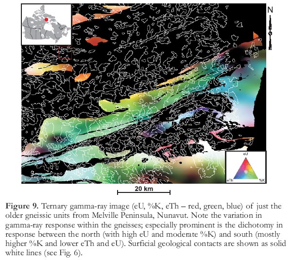
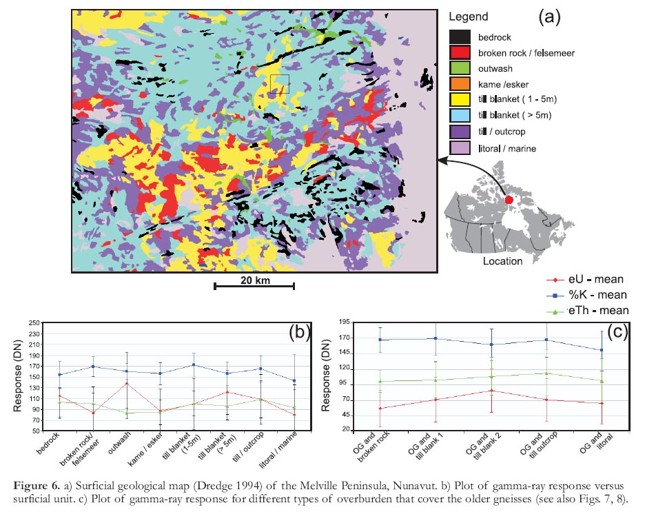
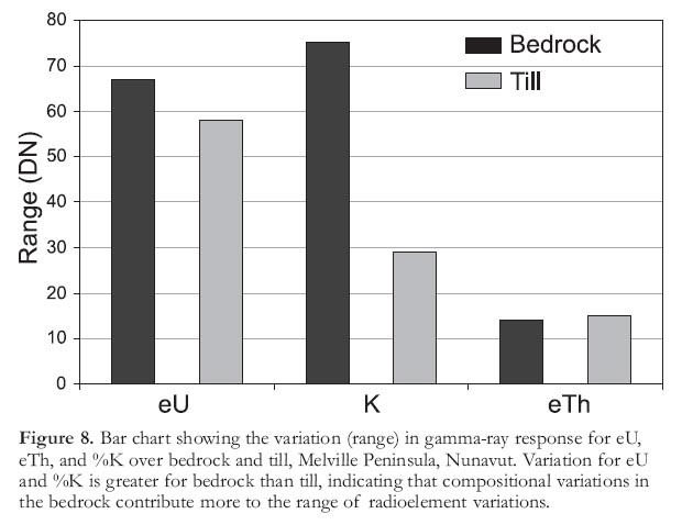
21 How much of the gamma-ray response can be attributed to bedrock and how much to surficial cover? This will again depend on the geological environment, but the Melville Peninsula study has resulted in some important observations. A plot of gamma-ray response for various mapped surficial units is shown in Figure 6. Clearly, a variation in the gamma-ray signal from different surficial units can be seen, especially for eU. However, the gamma-ray response pattern is also similar to the mapped bedrock geology, and produces a unique statistical response (Fig. 7). If one were to measure the variability of the surficial response over a single geological unit (Fig. 6b), a small part of the response can be attributed to variation in surface cover. However, the range of response, in this area, is greater for the bedrock than for the surface cover (Fig. 8). In fact, the gamma-ray data can show significant variations within a given rock unit (Fig. 9). This is useful for mapping purposes, as it points to discrepancies or inconsistencies in the geological field data that can be indicated on a predictive map and followed up in the field.
Figure 3. Variograms calculated from gamma-ray sample points acquired over the Melville Peninsula, Nunavut: a) eU along line; b) eU across line, c) eTh along line, and d) eTh across line. Note the differences in variogram structure (variation of sill, range, and nugget). e) The hypothetical (ideal) variogram shows the range, sill, and nugget. Range represents the distance at which sample points are no longer spatially associated. Sill represents the portion of the variogram where the model flattens, indicating where samples are no longer associated. Nugget represents small-scale variations at distances of less than the lag distance.DATA VISUALIZATION AND PROCESSING
Variables and Standard Survey Products
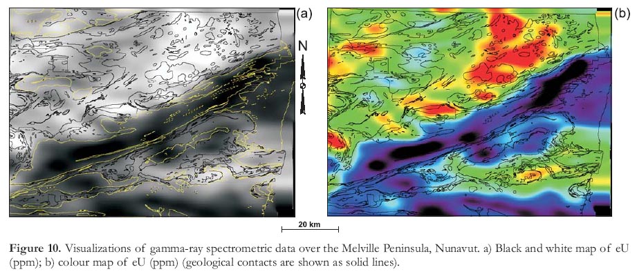
22 Airborne gamma-ray spectrometric data are usually represented by four measured variables, potassium (K, %), equivalent uranium (eU, ppm), equivalent thorium (eTh, ppm), and total air absorbed dose rate (nano Grays/hour: nGy/h). Five derived products are required to fully present the AGRS data. These include the three radioactive element ratios (eU/eTh, eU/K (ppm/%), and eTh/K (ppm/%)), the ternary radioactive element map (Broome et al. 1987), and the natural air absorbed dose rate (nGy/h). The complete display of all these data requires eight colour interval maps or images, including the ternary map. Examples of standard colour interval maps and ternary radioactive element maps are shown in Figures 10 and 11, respectively. In addition, a full suite of standard maps is presented in the Geological Survey of Canada's Remote Predictive Mapping Manual (Chapter 4, Figs. 4-16 and 4-17; Geological Survey of Canada 2008). Most map products require the data to be interpolated onto a regular grid. Many of the standard gridding algorithms are unsuited to AGRS data because of the inherent statistical variations. A suitable gridding algorithm is one that takes the average of all data points lying within a circular or elliptical area, inversely weighted for distance from the grid point or through the use of geostatistics (variogram in concert with kriging).
Figure 4. Interpolated ternary gamma-ray data acquired using different line spacings, and classified maps (unsupervised K-means algorithm) for an area underlain by the South Mountain Batholith in southwestern Nova Scotia (a and b); 5 km line spacing (c and d); 1 km line spacing (e and f); 250 m line spacing (g and h). In c), e) and g), eU (ppm), eTh (ppm), and K (%) are displayed through red, green, and blue colours, respectively; d), f) and h) are classified maps showing five distinct radioelement classes that define the South Mountain Batholith and surrounding area. Note the difference in the detail with respect to radioelement domains provided by the higher resolution data. However, the overall general patterns of radioelement zones are similar, regardless of spatial resolution.
Display large image of Figure 4
Table 3. Correlation of gamma-ray data acquired from different line spacings for eU (ppm), eTh (ppm), and K (%). The correlations between the data are moderate to strong with the lowest correlations between data with the largest difference in line spacing (i.e. 5 km vs. 250 m). Sample dataset is from southwestern Nova Scotia, the same as that used in Figure 4.
Display large image of Table 3
23 The ternary or three-component radioactive element map (Fig. 11) is an effective method of displaying variations in total radioactivity and the relative abundances of the three radioactive elements. Areas of the image with the same colour will have similar ratios of K, eU, eTh, and the intensity of that colour is a measure of the total radioactivity. This allows the map to represent the radioactive element distribution better than any of the other single variable or ratio maps. The ternary map is often easier to work with to get an overview of the distribution of radioactivity; however, it does not replace the more detailed, quantitative information available on the other seven maps (total or natural air absorbed dose rate, K, eU, eTh, eU/eTh, eU/K, and eTh/K).
24 Often, depending on the complexity of the geology, subtle variations in K, U, and/or Th may not be readily apparent. For these reasons, the proper interpretation of GRS data requires the examination of all of the measured variables and associated derived products. Ratio maps (Fig. 11b) can enhance or reinforce subtle variations in the measured variables, which can be particularly important, especially when dealing with varying intensities of alteration associated with a mineralizing process. For example, potassium alteration (enrichment) associated with certain types of mineral deposits may occur in host rocks with normally low to moderate levels of K, resulting in a high total K signature. This would be easily recognized if this alteration occurred in isolation. However, there may be normal, high-K rock types in close proximity to the altered rocks. In this situation, the K associated with the alteration may not be distinguishable from other high-K rock types. The ratio maps, in particular eTh/K, can be a sensitive indicator of K alteration associated with mineralization and can be used as a direct indicator of mineralization. The addition of K associated with alteration will normally result in low eTh/K because thorium is relatively immobile and its concentration remains constant. Shives et al. (1995, 1997) present a number of case histories that demonstrate the use of AGRS and GGRS to map potassium alteration associated with different styles of mineralization, including volcanogenic massive sulphides, polymetallic, magmatic-hydrothermal (Au–Co–Cu–Bi– W–As (Olympic Dam-type)), and porphyry Cu–Au–(Mo) deposits. On a regional scale, subtle variations in the measured variables, which are reinforced on the ratio maps, have been shown on maps of eU, eTh, and eU/eTh for southern Nova Scotia (Ford and O'Reilly 1985; Ford et al. 1989). Within the peraluminous granitic rocks of southern Nova Scotia, uranium concentrations generally increase and thorium concentrations decrease with increasing magmatic differentiation, resulting in abnormally high eU/eTh associated with the most evolved parts of these granitic intrusions.
Figure 5. Part of a gridded eU image showing a) profile locations, and b) an associated eU profile (along line) comparing eU derived from the interpolated grid. Note the smoothing effect due to the interpolation process (profile data are in blue and gridded data are in magenta).
Display large image of Figure 5
Display large image of Figure 6

Display large image of Figure 7
Display large image of Figure 8
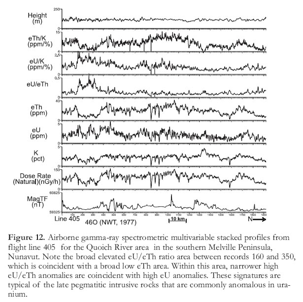
25 While gridding (interpolating) GRS data to produce colour interval maps or images, it is important to visually represent the geographic variations of a single variable. In contrast, a multivariable stacked-profile display (Fig. 12) is an essential tool for the visual analysis of all variables at each sample point. A stacked-profile presentation format permits the viewing of point-to-point data for all variables (measured and derived). Gridding airborne gamma-ray spectrometric data, particularly if the data were collected with a wide flight line spacing, requires a significant amount of interpolation, which will result in the loss of some detailed point-to-point information. Viewing of the point-to-point or line data in a stacked-profile format (Fig. 12) requires only a minimum amount of along-line filtering, thereby preserving more of the detailed point-to-point information.
Figure 9. Ternary gamma-ray image (eU, %K, eTh – red, green, blue) of just the older gneissic units from Melville Peninsula, Nunavut. Note the variation in gamma-ray response within the gneisses; especially prominent is the dichotomy in response between the north (with high eU and moderate %K) and south (mostly higher %K and lower eTh and eU). Surficial geological contacts are shown as solid white lines (see Fig. 6).Data Visualization
Single Band
26 Gamma-ray data can be presented as profiles (Figs. 5 and 12), as gridded black and white images, or as coloured images (Fig. 10), and the data usually vary over a narrow range of values compared with other geophysical (e.g. total-magnetic field) data. The data can be displayed as an image in concentration units or contrast-stretched to a byte format. The advantage of colour images is that the human eye can distinguish a much larger range of colours compared to black and white tones.
Multiband
27 Like optical LANDSAT and/or multi-beam radar data, gamma-ray channels (bands) can be displayed as ternary colour composite images (Fig. 11), allowing for the interpretation of three channels of elemental or ratio data using an additive mix of the primary colours (red-green-blue) of the computer display system.
Figure 10. Visualizations of gamma-ray spectrometric data over the Melville Peninsula, Nunavut. a) Black and white map of eU (ppm); b) colour map of eU (ppm) (geological contacts are shown as solid lines).Enhancement
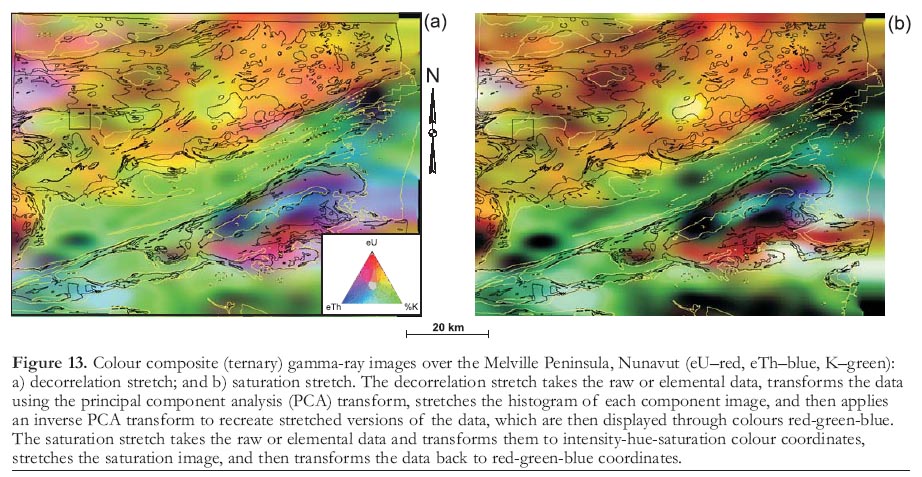
28 Like any raster-based dataset, the data can be contrast-stretched to improve its dynamic range. A decorrelation and/or saturation stretch (Gillespie et al. 1986), often applied to improve the colour range of LANDSAT data, can also be applied to gamma-ray data using most image analysis systems (Fig. 13). These stretches are more than simple arithmetic transforms that utilize simple mathematical functions (linear, square root, etc.) to transform the data. They involve either a multivariate statistical transform of the data (decor-relation stretch) or a colour-space transform (saturation stretch). In both cases the goal is the same: to provide an image in which subtle geological features are enhanced though a wide range of hues.
Figure 11. Colour composite (ternary) gamma-ray images over the Melville Peninsula, Nunavut. a) Raw (elemental) data (eU–red, eTh–blue, K–green). Note the major geological/tectonic divisions (A–pelitic gneiss and pegmatites, B–older gneiss, C–supracrustals); b) ratio data (U/K–red, Th/K–blue, U/Th–green) (geological contacts are shown as solid lines).Figure 12. Airborne gamma-ray spectrometric multivariable stacked profiles from flight line 405 for the Quoich River area in the southern Melville Peninsula, Nunavut. Note the broad elevated eU/eTh ratio area between records 160 and 350, which is coincident with a broad low eTh area. Within this area, narrower high eU/eTh anomalies are coincident with high eU anomalies. These signatures are typical of the late pegmatitic intrusive rocks that are commonly anomalous in uranium.Fusion
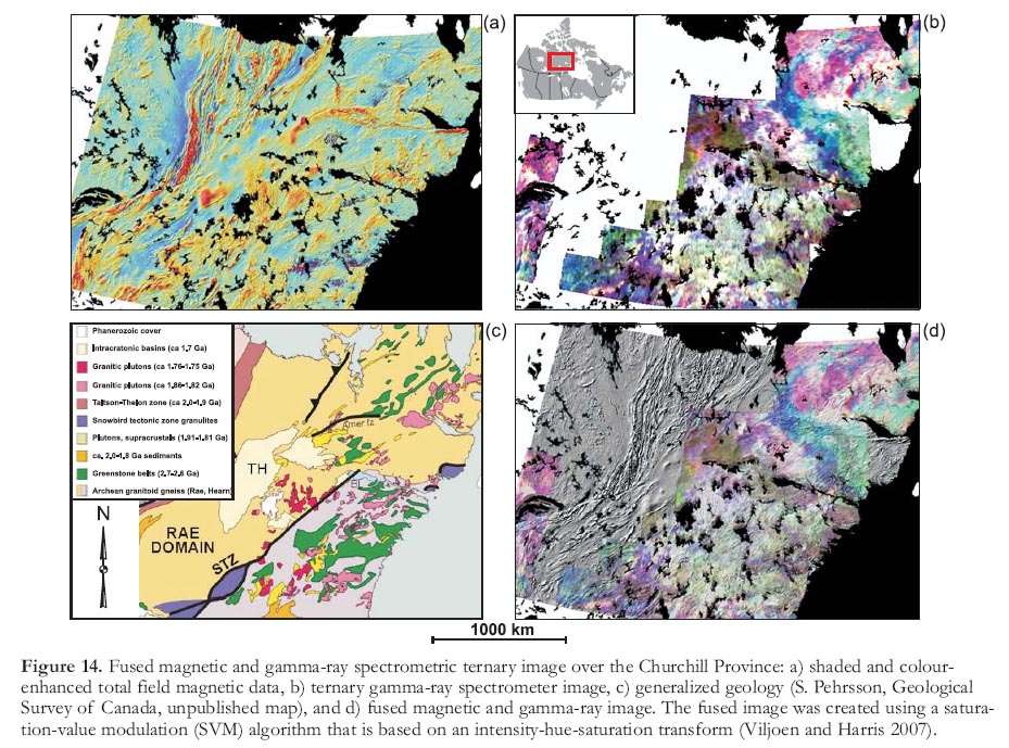
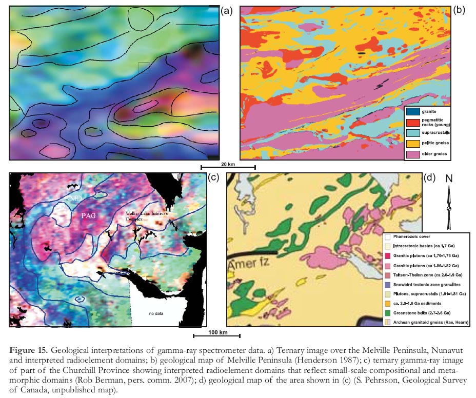
29 Like optical and microwave data, gamma-ray data may be fused with other types of remotely sensed information to create complementary imagery from the combined datasets. A fusion of gamma-ray and magnetic data (Fig. 14) often provides an image in which many geological features can be identified including radioelement domains (Fig. 15), faults, lineaments, plutons (Fig. 4), various rock units, and, in some cases, metamorphic domains (Fig. 15c).
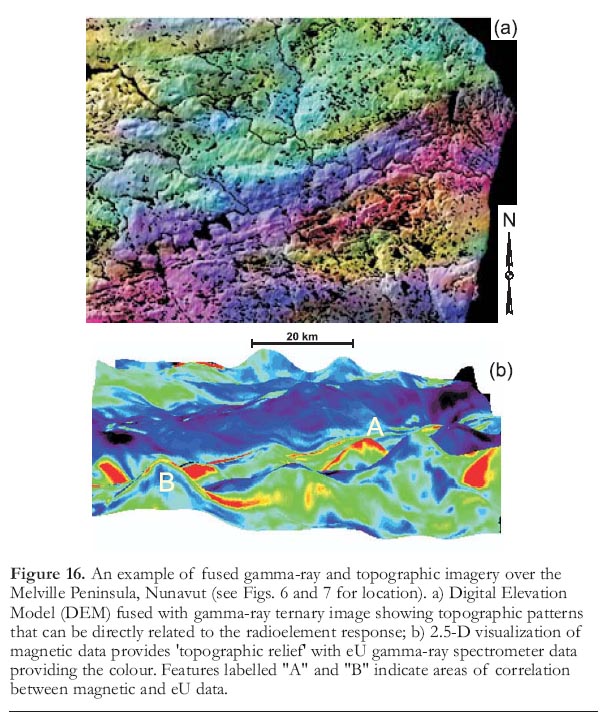
30 Gamma-ray data can also be fused with topographic data creating, an image in which potential gamma-ray anomalies can be directly compared to topographic patterns (Fig. 16a). This can be applied to help determine the source of gamma-ray anomalies. Gamma-ray data can also be fused with other geophysical variables, such as total magnetic field data or other gamma-ray images; e.g. eTh/K on K may potentially illustrate the location of potassium alteration zones.
2.5-Dimensional Visualizations
31 Different perspectives (e.g. 2.5-D) can be employed to not only fuse different data types but also to effectively visualize the relationships (both spatial and signature response) between them. Figure 16b shows a 2.5-D perspective image in which the relief reflects the magnetic total field and the colour reflects eU response over the Melville Peninsula, Nunavut. Correlations between the two data types can be seen over the supracrustal rocks (labelled A and B on Fig. 16b).
Figure 13. Colour composite (ternary) gamma-ray images over the Melville Peninsula, Nunavut (eU–red, eTh–blue, K–green): a) decorrelation stretch; and b) saturation stretch. The decorrelation stretch takes the raw or elemental data, transforms the data using the principal component analysis (PCA) transform, stretches the histogram of each component image, and then applies an inverse PCA transform to recreate stretched versions of the data, which are then displayed through colours red-green-blue. The saturation stretch takes the raw or elemental data and transforms them to intensity-hue-saturation colour coordinates, stretches the saturation image, and then transforms the data back to red-green-blue coordinates.
Display large image of Figure 13
Computer-Assisted Analysis
32 Gamma-ray data often comprise 7 channels of data, as mentioned above; hence, multivariate processing techniques can be applied to the data both for enhancement and classification purposes.
Principal Component Analysis
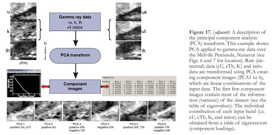
33 The principal component analysis (PCA) transform can be applied to make a reduced dataset comprising a series of component images that are a linear combination of all the gamma-ray data (Fig. 17). Individually, these component images often reveal geological information, but when combined in colour ternary images (Fig. 18), geological features are often enhanced by variations in colour.
Classification
34 The computer can be used to enhance gamma-ray data to create images for visual interpretation, as already discussed. However, the same classification techniques that are applied to LANDSAT and radar data can also be applied to gamma-ray data to automatically or semi-automatically create predictive maps.
Unsupervised
35 Various combinations of the gamma-ray data channels can be classified using an unsupervised classification algorithm to produce a thematic map of radioelement domains (classes) that show a distinct statistical separation (Fig. 19). The advantage of this approach is that it requires little input by the geologist other than specifying the number of classes. In many cases, this type of predictive map reveals patterns that can be directly related to lithological variations.
Supervised
36 Supervised classification involves the use of 'training' area statistics to characterize each rock type to be classified. These signatures are then used to classify the image into classes that have similar statistics to the training areas (Fig. 20). The results of a supervised classification (using a maximum likelihood algorithm) of major tectonic divisions over the Melville Peninsula, Nunavut, using a number of combinations of gamma-ray channels, as well as total field magnetic data, is presented in Figure 21. Using all GRS channels, a classification accuracy of close to 70% can be achieved for the major tectonic units. The misclassified areas (30%) are characterized by variations in gamma-ray response resulting from both surficial and bedrock variations.
37 Different supervised classification algorithms are available and at present much emphasis is being placed on neural network classifiers that are quite robust and often lead to very positive results. Figure 22 presents a neural network classification of litho-logical units (as opposed to major tec-tonic units) in the Melville Peninsula. In this example, a 64% classification accuracy of the lithological units was achieved when using just eU, eTh, and K. This increased to 70% when the magnetic data were included.
Figure 16. An example of fused gamma-ray and topographic imagery over the Melville Peninsula, Nunavut (see Figs. 6 and 7 for location). a) Digital Elevation Model (DEM) fused with gamma-ray ternary image showing topographic patterns that can be directly related to the radioelement response; b) 2.5-D visualization of magnetic data provides 'topographic relief' with eU gamma-ray spectrometer data providing the colour. Features labelled "A" and "B" indicate areas of correlation between magnetic and eU data.
Display large image of Figure 16
Display large image of Figure 17

Display large image of Figure 18
CONCLUSIONS
38 The ability of gamma-ray spectrometry to map the distribution of potassium, uranium, and thorium at the surface of the Earth provides powerful assistance for regional and local bedrock and surficial geological mapping. Important direct and indirect exploration guidance in a wide variety of geological settings is also provided, as is important information for environmental radiation monitoring and land-use planning.
39 Data enhancement and presentation methods can provide valuable interpretation assistance for gamma-ray spectrometric data. Ratio maps, including ternary K-U-Th colour presentations, are useful but, in the absence of corresponding radioelement concentration maps, are ambiguous. Flight line data, presented as stacked profiles, provide more detail than the inherently smoothed contour maps.
40 Proper interpretation of gamma-ray spectrometric data requires a clear understanding of petrology, surficial and bedrock geology, and geo-chemistry, as well as the gamma-ray spectrometric method itself. Despite the availability of large quantities of airborne gamma-ray spectrometric data collected since the 1970s and the development and publication of numerous case histories that clearly demonstrate the application to mapping and mineral exploration, the technique remains under-utilized and poorly understood by many potential users. The challenge remains to further develop techniques and case histories that continue to illustrate the broad range of applications, and to effectively disseminate this knowledge.
Figure 21. Supervised classification (prediction) of major tectonic divisions using a maximum likelihood algorithm applied to gamma-ray and magnetic data for the Melville Peninsula, Nunavut (see Figs. 6 and 7 for location). Training samples for each of the major tectonic units were gathered from legacy field data (point locations). Some of these were used for classification purposes whereas others were used for validation (cross-correlation) purposes . The accuracy, when compared to the check training sites, varied from close to 60% accuracy, when just using eTh, eU, and K for classification, to 72% when using both gamma-ray data (raw or elemental + ratios) and magnetic data.Figure 22. Supervised classification (prediction) of geological units using a neural network algorithm applied to gamma-ray and magnetic data over the Melville Peninsula, Nunavut (see Figure 7 for location). Training samples for each of the major units were gathered from the geological map areas. Some of these were used for classification purposes, whereas others were used for validation (cross-correlation) purposes. Accuracies, when compared to the check training sites, varied from 56% using the gamma-ratio data to 70% using both gamma-ray data (raw (elemental) + ratios) and magnetic data.ACKNOWLEDGEMENTS
This work was carried out and funded under the Remote Predictive Mapping Project, part of NRCAN's Earth Sciences Sector's (ESS) Northern Minerals Development Program. This paper is GSC contribution # 20070579. The authors wish to express their appreciation to John Spray and the editorial staff of Geoscience Canada for their very constructive comments to improve this manuscript.REFERENCES
Broome, J., Carson, J.M., Grant, J.A., and Ford, K.L., 1987, A modified ternary radioelement mapping technique and its application to the south coast of Newfoundland: Geological Survey of Canada, Paper 87-14, scale 1:100 000.
Dickson, B.L., and Scott, K.M., 1997, Interpretation of aerial gamma-ray surveys–adding the geochemical factors: Australian Geological Survey Organization, Journal of Australian Geology and Geophysics, v. 17, p. 187-200.
Dredge, L.A., 1994, Surficial geology, Barrow River, District of Franklin, Northwest Territories: Geological Survey of Canada, Map 1849A, scale 1:200 000.
Ford, K.L., and O'Reilly, G.A., 1985, Airborne gamma-ray spectrometric surveys as an indicator of granophile element specialization and associated mineral deposits in the granitic rocks of the Meguma Zone of Nova Scotia, Canada, in High Heat Production (HHP) Granites, Hydrothermal Circulation and Ore Genesis, papers presented at the High Heat Production (HHP) Granites, Hydrothermal Circulation and Ore Genesis Conference: The Institution of Mining and Metallurgy, London, England, p. 113-133.
Ford, K.L., MacDonald, M.A., Finck, P.W., Boner, F.J., Ham, L.J., Horne, R.J. Corey, M.C., and Graves, R.M., 1989, Airborne gamma ray spectrometry, and bedrock and surficial geology of the Davis Lake Pluton, in Mines and Minerals, Report of Activities 1989, Part A: Nova Scotia Department of Mines and Energy, Report 89-3.
Geological Survey of Canada, 2008, Remote Predictive Mapping: An Aid for Northern Mapping, Geological Survey of Canada Open File Report 5643, DVD, Natural Resources Canada.
Gillespie, A. R., Kahle, A.B., and Walker, R.E., 1986, Color enhancement of highly correlated images. I. Decorrelation and HIS contrast stretches: Remote Sensing of Environment, v. 20, p. 209-235.
Grasty, R.L., 1979, Gamma-ray spectrometric methods in uranium exploration–theory and operation procedures, in P.J. Hood, ed., Geophysics and Geochemistry in the Search for Metallic Ores: Geological Survey of Canada, Economic Geology Report 31, p. 147-162.
Grasty, R.L., and Minty, B.R.S., 1995, A guide to the technical specifications for airborne gamma-ray surveys: Australian Geological Survey Organisation, Record 1995/60, 89 p.
Grasty, R.L., Mellander, H., and Parker M., 1991, Airborne gamma-ray spectrometer surveying: International Atomic Energy Agency, Technical Report Series 323, Vienna, 97 p.
Henderson, J.R., 1987, Geology, southeastern Melville Peninsula, District of Franklin, Northwest Territories: Geological Survey of Canada, Map 1655A, scale 1:100 000.
Horsfall, K.R., 1997, Airborne magnetic and gamma-ray data acquisition: Australian Geological Survey Organization, Journal of Australian Geology and Geophysics, v. 17, p. 23-30.
Hovgaard, J. and Grasty, R.L., 1997, Reducing Statistical Noise in Airborne Gamma-Ray Data Through Spectral Component Analysis, in A.G. Gubins, ed., Proceedings of Exploration 97, Fourth Decennial International Conference on Mineral Exploration: Geophysics and Geochemistry at the Millennium, p. 753-764.
International Atomic Energy Agency, 2003, Guidelines for radioelement mapping using gamma ray spectrometry data: International Atomic Energy Agency, TECDOC-1363, 173 p.
Killeen, P.G., 1979, Gamma-ray spectro-metric methods in uranium exploration–application and interpretation, in P.J. Hood, ed., Geophysics and Geo-chemistry in Search for Metallic Ores: Geological Survey of Canada, Economic Geology Report 31, p. 163-230.
Minty, B.R.S., 1997, Fundamentals of airborne gamma-ray spectrometry: Australian Geological Survey Organization, Journal of Australian Geology and Geophysics, v. 17, p. 39-50.
Minty, B.R.S., Luyendyk, A.P.J., and Brodie, R.C., 1997, Calibration and data processing for airborne gamma-ray spec-trometry: Australian Geological Survey Organization, Journal of Australian Geology and Geophysics, v. 17, p. 51-62.
Shives, R.B.K., Ford, K.L., and Charbonneau, B.W., 1995, Applications of gamma-ray spectrometric/magnetic/ VLF-EM surveys–Workshop Manual: Geological Survey of Canada, Open File 3061, 82 p.
Shives, R.B.K., Charbonneau, B.W., and Ford, K.L., 1997, The detection of potassic alteration by gamma-ray spec-trometry–recognition of alteration related to mineralization, in A.G. Gubins, ed., Proceedings of Exploration 97, Fourth Decennial International Conference on Mineral Exploration: Geophysics and Geochemistry at the Millennium, p. 741-752.
Viljoen, D., and Harris, J.R., 2007, Saturation and value modulation (SVM): A new method for integrating color and grayscale imagery, in D.R. Soller, ed., Digital Mapping Techniques '06–Workshop Proceedings: United States Geological Survey, Open File Report 2007-1285.
Wilford, J.R., Bierwirth, P.N., and Craig, M.A., 1997, Application of airborne gamma-ray spectrometry in soil/regolith mapping and applied geomorphology: Australian Geological Survey Organization, Journal of Australian Geology and Geophysics, v. 17, p. 201-216.

